
Join thin sheet metal by matching the joint to access, load direction and the sheet’s ability to resist local damage. Screws suit removable covers; blind rivets allow one-sided installation; spot welds suit accessible overlaps; adhesives spread load over a prepared overlap. Validate the shortlist on the actual material stack before production.
This guide focuses on steel sheet assemblies, with cautions for mixed metals. “Thin” has no universal joining cutoff. Record actual thickness and material grade; a gauge number alone cannot define the joint. The broader sheet-metal fabrication workflow explains how cutting and forming affect assembly.
1. Define the joint before choosing a tool
Record the grade, thickness of each layer, coating, overlap, edge position and permitted surface marks. Add the load direction, vibration, temperature, wet exposure, sealing requirement and expected disassembly. Check tool, electrode, die and backing-piece access in the formed assembly.
Distinguish sheet thickness from the complete clamped stack. Coatings, washers and permitted interlayers may affect fastener grip and assembly fit. Use decimal millimetres or inches and identify the measurement basis. US gauge conventions and UK, Australian or Canadian sheet descriptions do not supply a joining specification; see choosing sheet thickness .
2. Shortlist methods by access and service
| Method | Useful starting point | Constraint to resolve |
|---|---|---|
| Screws or bolts | Removable cover, adjustable assembly | Thread engagement, sheet pull-through and access to the nut or insert |
| Blind rivets | Permanent overlap with one-sided setting access | Hole, grip range, blind-side clearance and local sheet strength |
| Resistance spot welding | Repeated overlapping steel joints with electrode access | Material stack, electrode force, weld schedule and visible indentations |
| Arc or laser welding | Welded seam where geometry and finish require it | Fit-up, burn-through, distortion and a qualified process |
| Clinching or self-piercing riveting | Repeated cold-joined overlaps with punch-and-die access | Formability, layer order, tooling and joint protrusion |
| Adhesive or hybrid joint | Broad overlap, mixed materials or low visible marking | Surface compatibility, peel loading, cure and environmental durability |
Scroll within the table to see all columns →
For a removable cover, start with a screw and a suitable captive nut, rivet nut or other designed thread feature. A tapped hole in very thin sheet may have insufficient engagement. Check insert installation and resistance to pull-out and rotation. A self-tapping screw also needs a verified hole, material thickness and tightening window.
Blind rivets are set from one side, but the unobserved side still needs room for the rivet to form. Select a specific fastener by its published grip range, recommended hole, material and head configuration. Check the installed joint against the sheet’s bearing, tear-out and pull-through resistance. A catalogue fastener tensile rating alone cannot establish panel capacity. Deburr holes and remove swarf; drilling stainless sheet needs particular attention to tool control and workholding.
3. Design for how thin sheet fails
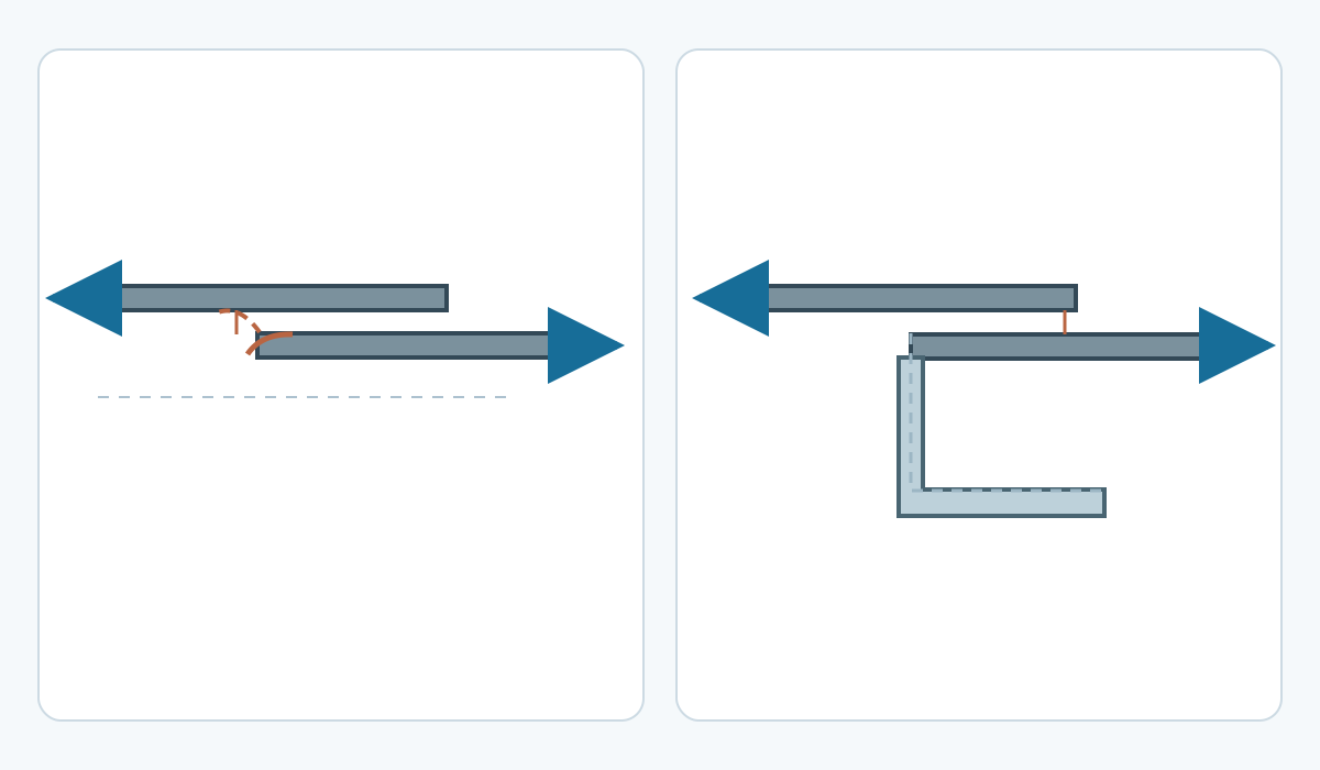
The offset between overlapping sheets lets an applied load bend and rotate a single-lap joint. That rotation may peel an adhesive edge or pry on a fastener even when the applied force appears parallel to the sheet. Place the joint near a supporting flange where practical and keep unsupported sheet bending under control.
| Observed failure | What to investigate | Possible design response |
|---|---|---|
| Elongated hole or torn edge | Sheet bearing, edge ligament and load distribution | Revise the layout or reinforce the load path |
| Head pulled through the sheet | Local bending and bearing area | Qualify a larger bearing feature or backing support |
| Opening at a bonded edge | Peel, contamination, coating separation or incomplete cure | Support the edge and correct the bonding process |
| Crack or distortion near a point joint | Material condition, tool/weld settings and joint spacing | Adjust the process and revalidate the assembled geometry |
Scroll within the table to see all columns →
Choose fastener pitch, edge distance and weld layout from the applicable design method, supplier data and trials. Extra holes reduce the remaining sheet section, and a stiffer joint can move deformation into an unsupported panel. Recheck the whole load path when changing the layout.
4. Control heat and forming effects
Resistance spot welding makes a permanent fused joint under electrode pressure. Conventional opposing-electrode equipment needs access to both outer faces. The grade, layer thicknesses, coating and electrode condition determine the qualified welding schedule; one current setting cannot cover every thin sheet. ISO 14373:2024 addresses defined low-carbon-steel spot-welding applications; confirm the full scope before using it.
For arc or laser seams, control the gap, restraint and heat input through the chosen procedure. A trial should expose burn-through, incomplete fusion and distortion after clamps are removed. A sequence of isolated welds does not create a sealed seam. Use the dedicated guides for stainless welding and galvanized welding when selecting preparation and finishing details.
Clinching forms an interlock from the sheets; self-piercing riveting adds a rivet driven and flared into the stack. Both depend on the approved material combination, layer order and tooling. Inspect trial sections and the supplier’s control dimensions. Cold forming can still crack a hard sheet, mark a finish or damage a coating. Folded seams and hems are further options where the edge geometry permits them; validate opening resistance and sealing separately.
5. Qualify surfaces, adhesives and corrosion protection
An adhesive transfers load through every layer between the sheets. Oil, weak paint or a poorly attached coating can become the weak interface. Qualify the actual surface condition and follow the selected product’s cleaning, pretreatment, mixing, bondline and curing instructions. Hold the assembly in the specified position and curing conditions until the product permits handling. Apply qualification loads only at the required cure state.
Use an overlap that limits peel and cleavage, and verify sustained-load behaviour, temperature and moisture exposure. Supplier lap-shear data describe particular test conditions. ISO 4587:2003 provides a lap-shear test method; its results are not joint design allowables. A hybrid joint combines adhesive with a fastener, clinch or weld. Validate the combined sequence, including adhesive displacement and any welding compatibility; the two published strengths cannot simply be added.
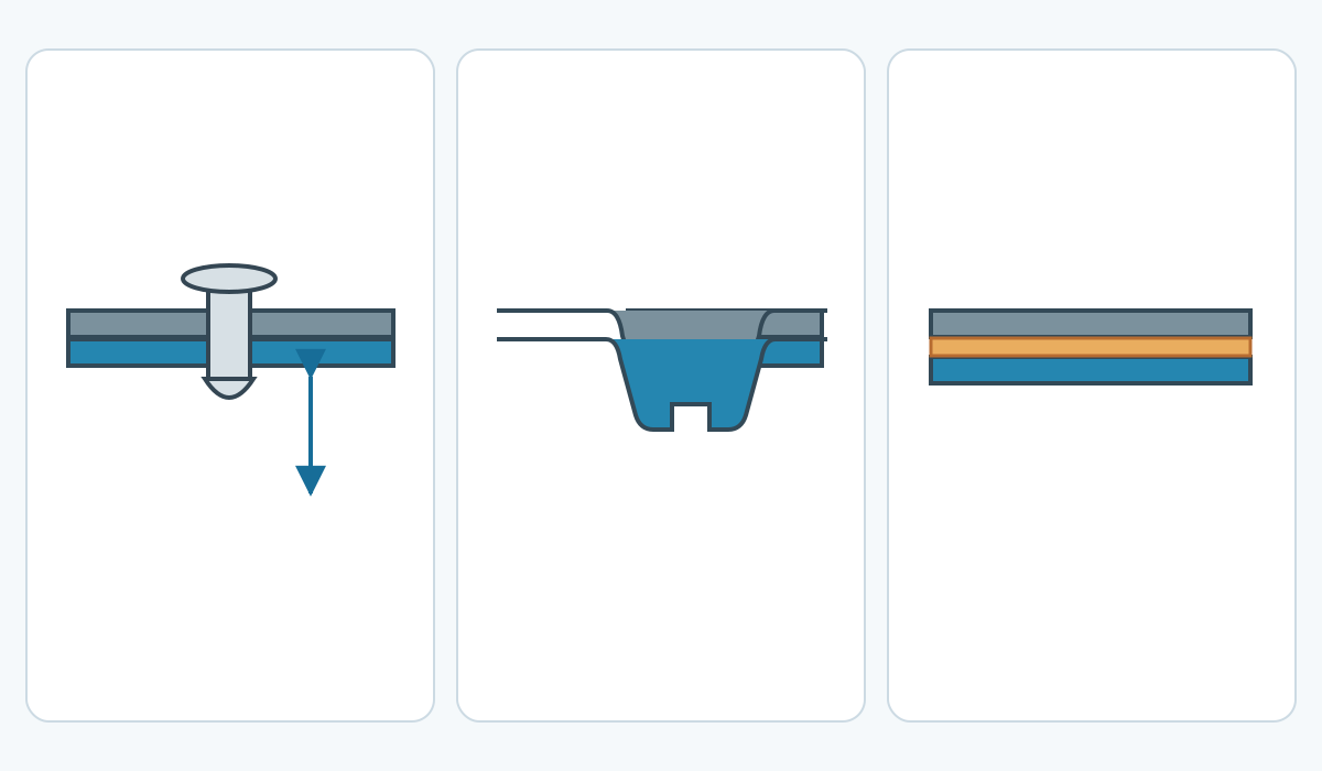
For mixed metals exposed to an electrolyte, assess galvanic compatibility and any required isolation. Protect drilled edges, damaged zinc and inaccessible crevices using a compatible system; plan drainage and sealing before closing the assembly. An adhesive layer may assist isolation only when its continuity and the remaining metal contacts have been addressed. Fastener penetrations and damaged edges can still provide conductive paths.
6. Validate a trial and release the process
Use coupons and an assembled trial that represent production grade, coating, thickness tolerances, holes, overlap and surface preparation. Set acceptance criteria before testing: load and failure mode, permitted distortion, visible marks, leakage where required, and durability under the expected environment. Add fatigue or repeated opening tests where service demands them. Visual appearance alone cannot confirm internal weld fusion or bond durability.
Record the approved fastener and tool, hole or die details, tightening or setting controls, weld procedure, adhesive batch and cure, and corrosion repair. Establish inspection frequency and requalification triggers such as a new coating, different sheet grade or tool change. Use the governing design and fabrication requirements for safety-critical or regulated work.
Control sharp edges, drilling swarf, pinch points, adhesive exposure and hot-work hazards. Welding needs appropriate fume controls, including assessment of coatings; HSE’s guidance is a UK reference and local workplace requirements still apply.