
A clean hole in stainless sheet needs a sharp, suitable cutting tool, a workpiece that cannot spin or lift, and enough controlled feed for the edges to cut. Thin sheet makes the last part of the hole especially important: an unsupported exit can grab, distort the sheet or leave a large burr.
Start with the actual grade, thickness and hole requirement. Use the drill manufacturer’s data for that combination, then prove the setup on representative material. A speed copied from another job can be unsuitable even when both sheets are described as “stainless.”
1. Define the material and the finished hole
Record the grade, material condition, measured thickness, hole diameter, position tolerance and required finish. A decimal thickness in millimetres or inches avoids ambiguity when a drawing only gives a gauge. Check whether the hole is for simple clearance, a fitted component or a later operation such as tapping.
Austenitic grades such as 304 and 316 can develop a work-hardened surface during machining. Rubbing or repeated ineffective attempts can make the next cut harder. Heat also accelerates tool wear, so cooling and a cutting edge that actually removes material matter together. Do not treat local heating alone as the definition of work hardening.
Previously formed material, a damaged hole and an unknown alloy need separate assessment. Stop a stalled attempt and examine the tool and surface before trying again. A cosmetic panel also needs a plan for protecting its visible face and removing cutting-fluid residue.
2. Choose a drill that suits thin sheet
Tool material, point geometry, diameter, cutting length and machine stability all influence the choice. A cobalt-alloyed HSS drill rated for stainless is a practical option for many workshop jobs. Select the shortest suitable length. A gold-coloured coating alone does not establish a drill’s suitability.
| Hole and setup | Tool route to consider | What to verify |
|---|---|---|
| One small round hole | Stainless-rated twist drill | Point geometry, diameter and support at exit |
| Several diameters in thin sheet | Stainless-rated step drill | Maximum sheet thickness and usable step length |
| Larger opening | Hole saw or sheet cutter rated for stainless | Diameter range, pilot arrangement, torque and slug removal |
| Repeated precision holes on a rigid machine | Suitable production drill and finishing operation | Toolholder, runout, coolant and final tolerance |
Scroll within the table to see all columns →
A step drill is limited by its own geometry and rating; the next step can enlarge the entry before the required diameter has cleared a thick sheet. Carbide tools require the setup their manufacturer specifies. They are not an automatic cure for a flexible panel or an unstable handheld drill.
A pilot hole is a tool-specific decision. Some self-centering designs start directly; others specify a pilot or spotting operation. Avoid a sequence of tiny diameter increases without a reason, and do not heavily punch a thin panel merely to stop wandering. A drilling jig or suitable spotting method may be the better option.
3. Clamp and support the sheet before starting
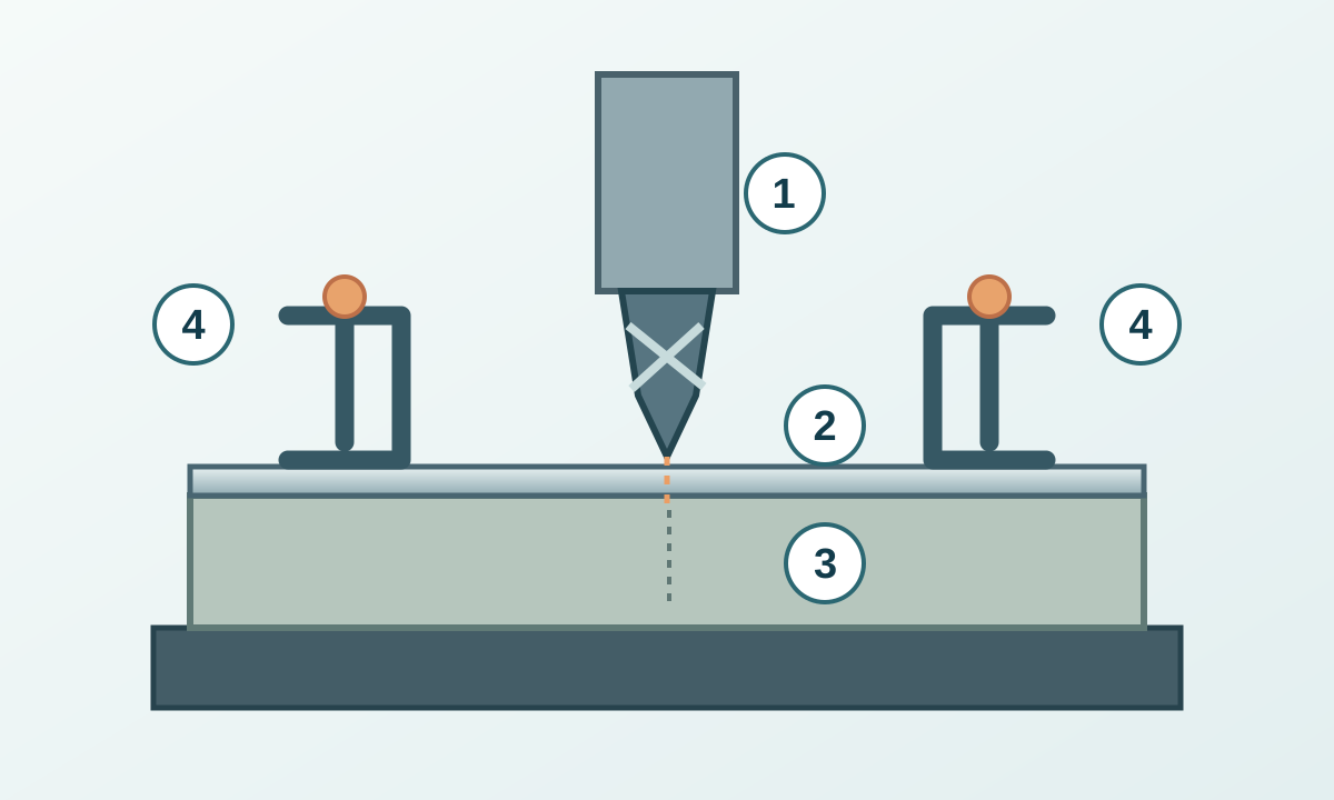
Choose a support arrangement that keeps the sheet flat near the hole and leaves a safe path below the drill. A clean sacrificial backing plate or suitable backing block can support the exit. Clamp the sheet and support securely to the table or fixture, without distorting the part. Plan for the bit to enter the sacrificial material without striking the table or hidden fasteners.
Never hold the sheet by hand. Remove the chuck key, fit the guards and wear appropriate eye protection. At a drill press, keep gloves, loose clothing, jewellery and hair away from rotating parts. Protective gloves used to carry sharp sheet must be removed before operating the rotating machine. Follow the machine manual and local training requirements.
For installed panels, also check the concealed side for wiring, pipes and other hazards. If access prevents secure support or safe inspection, remove the part or choose an approved alternative process.
4. Set cutting speed, feed and lubrication together
Start from current data for the exact drill, grade and condition. Cutting speed describes motion at the cutting diameter; spindle speed is revolutions per minute. Larger diameters need fewer revolutions for the same cutting speed.
With cutting speed Vc in m/min and diameter D in mm:
n = 1000 × Vc ÷ (π × D)
If the applicable tool data specified 15 m/min for a 6 mm drill, the conversion would give about 796 rpm. Those assumed inputs illustrate the calculation; they are not recommended settings for every stainless sheet. For a step drill or hole saw, follow its diameter-dependent speed instructions.
Feed per revolution and feed per minute are different quantities. For machine feed, feed rate in mm/min = rpm × feed in mm/rev. Use consistent units and do not add a flute-count multiplier to a feed already given per revolution.
Apply a cutting fluid approved for the material, tool and machine. Arrange delivery before starting; do not reach past a rotating spindle to apply it. Consider the product’s safety instructions and the part’s cleaning requirements. A drill that spins without advancing needs diagnosis. Increasing hand force until the machine stalls is not a controlled feed strategy.
5. Drill with a controlled exit
- Check the marked location, tool security, fixture, backing and exit clearance with the machine stopped.
- Set the approved speed and prepare the lubrication. Keep the drill aligned with the intended hole axis.
- Begin with the starting method specified for the tool. Maintain cutting action without lingering against the surface.
- Watch for chip accumulation, changing sound, rising effort or sheet movement. Stop and correct an abnormal condition before continuing.
- As the drill breaks through, ease the feed pressure in a controlled way to limit grabbing. Keep the work clamped and the exit supported; avoid prolonged rubbing at the last edge.
- Stop the spindle completely before measuring, repositioning or clearing chips. Use a brush or suitable vacuum, not fingers.
A thin-sheet through-hole does not automatically require a deep-hole peck cycle. Follow the tool’s chip-clearing instructions when withdrawal is needed. Keep hands clear and re-enter in a controlled manner; repeated dwelling at the same surface can worsen the problem.
For tool changes, jam clearing or maintenance, follow the machine-specific isolation procedure. A stopped spindle alone is not a safe basis for entering a hazard area.
6. Diagnose the symptom before changing the settings
| Symptom | Checks to make with the machine stopped | Useful next step |
|---|---|---|
| Drill slips or no longer advances | Edge wear, unsuitable tool, work-hardened surface, incorrect rotation | Replace or restore the tool and reassess the starting method |
| Hole wanders or becomes oversized | Marking, runout, alignment, weak clamping | Correct location control and rigidity before another trial |
| Squeal, chatter or sheet flutter | Unsupported span, tool projection, loose fixture, cutting data | Improve support and verify the tool's operating range |
| Large exit burr or distorted lip | Backing contact, breakthrough control, worn edge | Restore support, check the edge and refine the exit |
| Repeated breakage or packed flutes | Chip evacuation, excessive load, misalignment | Stop the job and correct the cause before replacing another drill |
Scroll within the table to see all columns →
These are diagnostic leads, not proof of one cause. Sound and chip colour alone cannot approve a process. After a change, inspect a trial hole before continuing production.
7. Deburr, clean and inspect both faces
Remove the sharp edge with an appropriate deburring tool or controlled countersink operation. Keep the part secured and protect the required diameter and remaining sheet thickness. A large countersink can remove too much material from thin sheet; specify a chamfer only when the drawing requires it.

Check diameter and position with suitable measuring tools, then inspect roundness where specified, burrs on both faces, distortion and surface damage. Remove swarf and fluid residue with a process compatible with the intended service. Use clean tooling reserved for stainless where contamination control matters. Record the successful tool, speed, feed, support and inspection result for repeat work.
For repeated shapes, compare the requirements with sheet-metal punching . For the finish around a visible hole, see stainless-sheet polishing . Tool changes, material changes or worsening burrs require a renewed check rather than an automatic continuation of the old settings.