
Punching separates sheet metal with a punch and die. The process is fast and repeatable, yet the finished hole reflects several linked variables: material and thickness, punch size, die opening, tool sharpness, alignment, stripping, lubrication, machine condition and feature layout.
A stable setup starts with the drawing and the actual production material. Define the required hole or cutout, allowable burr, dimensional tolerance, surface condition and downstream operations, then qualify the tooling on a representative first piece.
Punching suits repeated holes and standard shapes when suitable tooling is available. In piercing, the hole is the required feature and the removed slug is scrap; in blanking, the removed piece is the product. Their dimensional and clearance choices can differ. Nibbling builds a contour from overlapping hits and leaves scallops that may need finishing. Compare laser cutting or another route when changing contours, tight edge requirements or tooling availability make punching impractical.
What a punched edge tells you
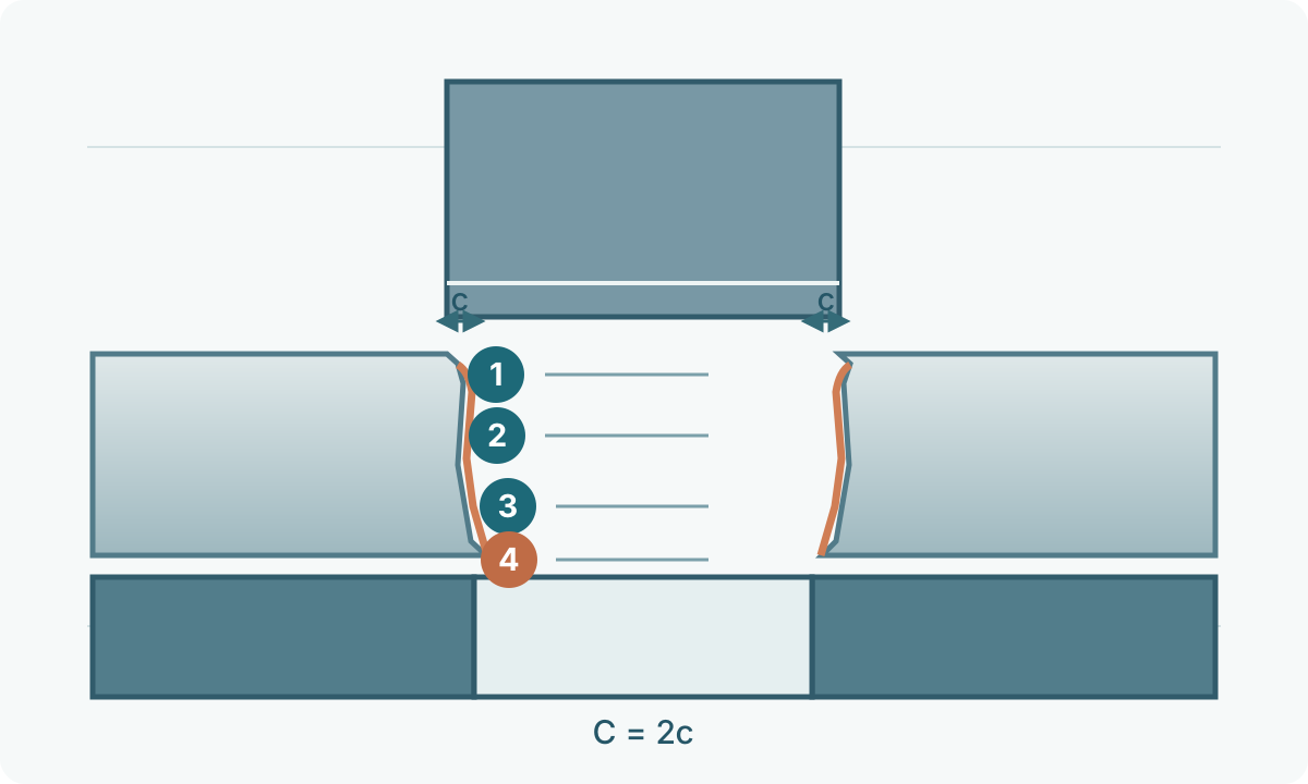
A punched edge normally contains rollover at the punch-entry side, a burnished zone, a fractured zone and a burr at the die-exit side. Their proportions change with material, clearance, tool condition and setup. A visually smooth edge by itself does not prove that the process is centered.
Inspect the hole and the slug together when diagnosing a setup. Fracture alignment, burr growth, uneven burnish or a one-sided pattern can reveal clearance, wear or alignment problems.
Start with material, thickness and feature requirements
Confirm grade or material family, actual thickness, coating or finish, expected strength range and any surface-protection requirement. Stainless steel, low-carbon steel, high-strength sheet and soft non-ferrous materials can need different clearances, lubrication and tooling strategies.
The drawing also controls the process. Record hole size and shape, positional tolerance, burr direction, critical edge condition, hole-to-edge and hole-to-hole spacing, nearby bends or formed features, and which face must remain cosmetic.
Avoid universal rules for minimum hole size or feature spacing. Tooling suppliers publish limits for particular systems, materials and thicknesses. When a feature approaches those limits, use the applicable tooling data and validate the part.
Where a punched edge will later be stretched or flanged, include that operation in the trial: a dimensionally acceptable hole can still have inadequate edge formability. High-strength grades need their own validated clearance and edge-quality data.
Set punch-to-die clearance deliberately
Die clearance is the gap that allows the material to fracture between punch and die. Some tooling suppliers report clearance per side; others report total clearance across both sides. The convention must be identified before a numeric value is applied.
Mate’s Technical Solutions Guide Rev E defines total clearance and provides different piercing and blanking values by material and thickness on printed page 3. Its 20–25% total-clearance advice appears in the tool-maintenance and rapid-wear troubleshooting material on printed page 13; it is supplier-specific troubleshooting guidance, not a universal setup band. Select the applicable current chart for the tool system, operation and material.
For a centered round punch, total clearance = die diameter − punch diameter, and clearance per side = total clearance ÷ 2. As an arithmetic example only, 20% total clearance on 2.0 mm sheet is 0.40 mm total, or 0.20 mm per side. A 10.00 mm punch would therefore pair geometrically with a 10.40 mm die opening. This illustrates the convention; production dimensions and finished-hole tolerances still need supplier approval and a trial.
Clearance that is too tight can raise punching force, create secondary shearing and accelerate tool wear. Excess clearance can increase rollover, fracture angle and burr. The practical target balances part quality, tool life, stripping and machine load.
Estimate force with a stated unit basis
For a flat-faced punch, a basic cutting-force estimate is F = L × t × τ, where L is the simultaneously cut perimeter, t is sheet thickness and τ is an appropriate shear-strength estimate for that material. With L and t in mm and τ in N/mm² (MPa), F is in N; divide by 1,000 for kN. Count all simultaneously cutting edges in cluster tooling. Do not substitute tensile strength directly or mix a supplier’s tonnage coefficient with a second shear-strength factor.
Illustrative calculation: L = 100 mm, t = 1.5 mm and assumed τ = 300 N/mm² give 45,000 N = 45 kN. The assumed strength is not a specification for a steel grade. This is about 4.59 metric tonne-force or 5.06 U.S. short ton-force. One metric tonne-force is 9.80665 kN; one U.S. short ton-force is approximately 8.89644 kN. Confirm what the machine’s “ton” rating means.
This estimate does not approve the job. Verify press and station/tool limits, stripping load, off-center loading and the manufacturer’s operating allowance. Wear can raise force. A shear-faced punch can reduce peak force, but Mate warns against relying on that reduction to bring an otherwise excessive job within press capacity.
Diagnose the edge before changing the program
| Observed result | First checks |
|---|---|
| Burr grows around the hole | Tool sharpness, die clearance, alignment, material change and tool wear |
| Burnish is uneven around the perimeter | Punch/die alignment, lateral load, tool damage and station condition |
| Hole is distorted or sheet pulls upward | Stripper support, thin-sheet support, clearance, feature layout and slug control |
| Tool wears unusually fast | Clearance, material strength, lubrication, galling, alignment and partial-hit loading |
Scroll within the table to see all columns →
Measure the dimensions that matter to the drawing. Hole size can shift with material, tool wear, springback and the measurement method. Burr height or edge condition should be evaluated with a defined acceptance criterion when it matters to assembly, coating, sealing or safety.
Control small holes, close features and distortion
Small punches have less cross-section to carry load and are more sensitive to misalignment, side loading and poor stripping. Thin sheet can also lift or distort around closely spaced features. Use the tooling maker’s minimum punch-size and thickness guidance for the specific system.
Feature layout affects process stability. Holes close to an edge, bend line, emboss or another punched feature can distort as the surrounding material loses support. Sequence, support and tool choice should be validated on the actual geometry.
For dense perforation or partial hits, monitor lateral loading and heat. A process that is acceptable for an isolated round hole may behave differently when many hits are made close together.
Protect tooling and keep the setup centered
Sharp, aligned tooling lowers unnecessary load and produces a more stable edge. Track punch and die condition instead of waiting for burr growth to become excessive. Regrind and restore tooling according to the tooling manufacturer’s limits and procedure.
Galling is more likely when material adheres to the punch under pressure and heat. Material choice, lubrication, tool finish, coatings and back taper can affect it. Any change intended to reduce galling should stay within the tool supplier’s approved configuration.
Check station alignment after tool damage, abnormal wear or a collision. Uneven edge patterns can come from alignment as well as clearance, so increasing die opening alone may leave the root cause in place.
A slug carried back up with the punch can mark the next part or damage the tool. Inspect slug evacuation and the approved retention/ejection system, die penetration, lubrication and magnetism after grinding. Use only the supplier’s remedies for the tooling involved. A jam or abnormal slug return requires a safe stop and the prescribed recovery procedure.
Qualify the first piece and hold the process
A practical setup sequence is:
- Verify drawing revision, material identity, actual thickness and surface condition.
- Confirm punch, die, stripper and station are the approved set and in serviceable condition.
- Check the clearance convention and select the supplier-approved starting clearance.
- Confirm machine capacity for the material, perimeter and operation using the press/tooling manufacturer’s method.
- Punch a representative first piece using the intended lubrication, support and sequence.
- Inspect dimensions, burr direction and height where specified, edge pattern, distortion and surface marking.
- Adjust one controlled variable at a time and repeat the first-piece check.
- Record the accepted tooling, clearance, material lot, program revision and inspection result.
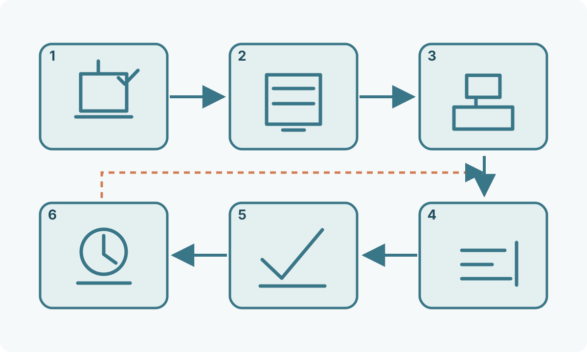
During production, trend burr, dimensions and tool condition. A gradual change often signals wear or material variation; a sudden one can indicate damage, alignment loss, slug problems or a setup change.
Keep guarding and machine limits in the process plan
Punch presses expose operators to the tool zone, moving sheet and ejected material. U.S. OSHA 29 CFR 1910.212 addresses general machine guarding. Mechanical power presses within the scope of 1910.217 have additional requirements; that section excludes hydraulic and pneumatic power presses. Apply the requirements for the actual machine and jurisdiction together with the manufacturer’s instructions.
Before reaching into a hazard area for jam clearing, tool changes or servicing, follow the employer’s machine-specific hazardous-energy procedure. U.S. OSHA 1910.147 addresses unexpected startup and stored-energy hazards during covered servicing. A stop button alone does not isolate energy. Safeguarding, training and approved maintenance procedures must remain effective; this guide is not a machine operating or safeguarding procedure.
Do not bypass guards, interlocks or approved tooling limits to recover output. If a feature exceeds the validated capability, change the tooling or process route.
For broader process selection, see How to Cut Sheet Metal . For straight-line blank preparation, use the Sheet Metal Shearing Guide . The sheet-metal fabrication overview shows how punching affects later forming, joining and finishing.