
A sheet-metal part is the result of a process chain, so every operation inherits decisions made upstream. Grade, thickness, flatness, coating, rolling direction and surface condition affect cutting and forming. Cut-edge quality influences later bending and joining. Welding can change shape and surface condition. Finishing may expose dimensional or contamination problems that were created much earlier.
A reliable fabrication plan therefore starts with the drawing and service requirements, then treats cutting, forming, joining, finishing and inspection as connected stages.
The fabrication workflow at a glance
| Stage | What happens | Controls that matter downstream |
|---|---|---|
| Material and planning | Confirm grade, condition, thickness, coating, finish, sheet size and drawing requirements | Actual thickness, material direction, tolerance basis, surface protection, traceability |
| Cutting / blanking | Create the flat blank, holes, slots and edge geometry | Cut accuracy, burr, heat-affected edge, taper, kerf, feature location |
| Forming | Bend, roll, stamp or otherwise reshape the blank | Inside radius, tooling, bend sequence, springback, rolling direction, surface marking |
| Joining | Assemble parts by welding, resistance joining, fasteners, clinching or another qualified method | Heat input, distortion, joint access, fixture strategy, coating or finish damage |
| Finishing | Deburr, clean, grind, pickle/passivate where applicable, paint, powder coat or repair a metallic coating | Final appearance, corrosion performance, cleanliness, dimensional effect |
| Inspection | Verify geometry, joints, surface condition and specified documentation | Drawing compliance and fitness for the next assembly or service step |
Scroll within the table to see all columns →
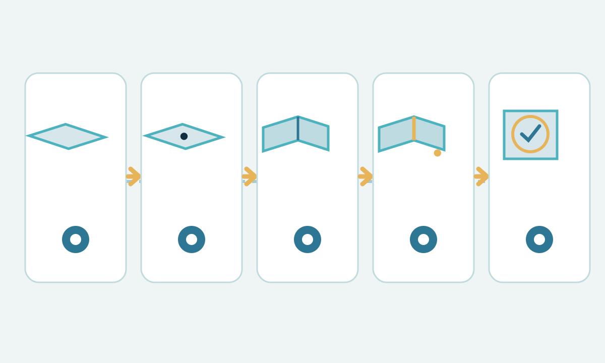
1. Translate the drawing into process requirements
Before choosing a machine, identify what the finished part must control. Typical inputs include material specification, nominal and allowable thickness, critical dimensions and datums, hole and slot requirements, bend geometry, surface finish, coating, weld or fastener requirements, quantity, cosmetic zones and inspection criteria.
This is also where ambiguous drawing language should be resolved. A dimensional requirement that is easy to meet on a flat blank may become difficult after several bends and a weld. A cosmetic surface may need film protection and dedicated handling from the first operation.
For purchasing and specification details, see how to specify steel sheet and coil .
2. Confirm the material before programming the process
Material identity influences nearly every later choice. Verify the grade and delivery condition, actual thickness range, coating or finish, and any directionality that matters to forming. Stainless, low-carbon sheet, high-strength steel, galvanized sheet and prepainted sheet can require different tooling, edge treatment, joining practice and surface protection.
Nominal gauge alone is weak process input because gauge systems vary by material and market. Engineering decisions are clearer when the drawing and machine setup use actual thickness in millimetres or inches. The steel sheet thickness guide covers that selection step in more detail.
3. Cutting creates the geometry that forming inherits
Sheet can be blanked with snips, shears, punches, saws, laser, plasma, waterjet or other equipment. The appropriate route depends on material, thickness, geometry, edge requirement, heat sensitivity, batch size and available capability.
The cut should be evaluated for the features that matter later: dimensional accuracy, burr direction and height, edge taper, dross, heat-affected condition, hole quality and local distortion. A burr located on a forming surface can mark tooling or initiate surface damage. Heat from a thermal process can also alter a narrow edge zone.
ISO 9013:2017 provides classifications and geometrical quality/tolerance terminology for specified thermal cuts produced by oxyfuel, plasma and laser processes. Its scope does not make it an automatic acceptance standard for every sheet-metal part; the drawing or delivery document has to invoke the relevant requirement.
For a process-by-process comparison, use How to Cut Sheet Metal .
4. Forming turns the flat pattern into the functional shape
Press-brake bending, hand braking, roll bending and stamping impose plastic deformation. Setup depends on grade, thickness, tooling geometry, bend direction, required inside radius, flange geometry and angle tolerance.
Flat-pattern dimensions must account for the material consumed by each bend. Springback then affects the relationship between tool motion and the unloaded final angle. Both effects depend on material and process conditions, so production values should come from qualified shop data, supplier guidance, tooling information or validated trials.
ISO 7438:2020 describes a bend test for metallic material test pieces. It is useful material-test context; it does not prescribe a universal production bend radius for every fabricated component.
Detailed setup considerations are covered in How to Bend Sheet Metal .
5. Joining can change both geometry and corrosion performance
A fabrication may use fusion welding, resistance spot welding, mechanical fasteners, clinching or another joining process. Joint choice depends on strength, fatigue, leak tightness, appearance, disassembly, access, production volume, coating and service environment.
Heat from welding can introduce shrinkage and distortion. It can also affect metallic coatings and the surface condition of stainless steel. Fixtures and weld sequence can reduce movement, although the final strategy has to be qualified for the actual joint and material. Mechanical joining avoids a weld heat-affected zone and can be useful where the design and loading permit it.
Plan access early. A fastener, welding torch or electrode needs space after the part has been bent; the most convenient joining sequence on a flat drawing can become inaccessible on the three-dimensional assembly.
6. Finishing is part of the process plan
Deburring and edge conditioning should be defined by function. Handling edges, sealing faces, coating edges and visible surfaces may have different requirements.
Finishing can include cleaning, grinding, brushing, polishing, pickling/passivation for suitable stainless applications, paint or powder coating, and repair of damaged metallic coatings under the governing specification. Keep stainless work isolated from carbon-steel contamination where the required surface condition demands it.
Finishing also changes what can be measured and repaired. Heavy grinding can modify edge geometry; coating adds thickness; aggressive cosmetic rework can erase a datum or soften a corner. Inspection planning should identify which dimensions are checked before finish and which are verified afterward.
7. Tolerances accumulate through the route
A final flange location can depend on blank length, feature position, bend-line location, bend angle, inside radius and earlier bends. Weld shrinkage may add another source of movement. Treating each operation independently can produce a part whose individual steps looked acceptable while the final assembly misses a critical datum.
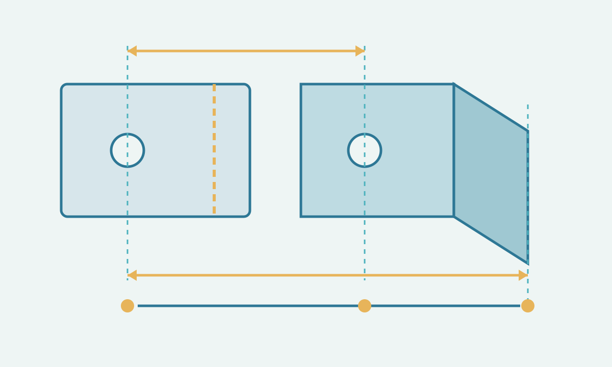
Place the tightest tolerances where they serve the function, identify inspection datums clearly and avoid assigning precision that the assembly does not need. Supplier capability and the applicable product/process specification should set realistic values.
8. Inspect the state that matters to the customer
A useful inspection plan follows the drawing and the manufacturing sequence. Depending on the part, it may verify:
- material identity and traceability;
- thickness and sheet condition;
- blank and hole geometry;
- bend angle, flange height and final envelope;
- weld size or joint condition where specified;
- surface finish, burrs and contamination;
- coating or post-treatment condition;
- documentation required by the order or quality plan.
Some dimensions are best checked before joining; others only make sense on the finished assembly. Define that timing in advance.
Process safety belongs in the routing
Cutting, punching, bending and rolling create point-of-operation and moving-workpiece hazards. In the United States, OSHA 29 CFR 1910.212 lists machines such as guillotine cutters, shears, power presses, saws and forming rolls among equipment that commonly requires point-of-operation guarding. OSHA’s powered press-brake guidance also highlights accidental cycling and movement of large workpieces.
Machine guarding, lockout procedures, fume control, laser safety, hot-work controls and personal protective equipment depend on the equipment and jurisdiction. Follow the machine manufacturer’s instructions, the site’s risk assessment and applicable local regulations.
What a fabrication quote should define
A useful request for quotation gives the fabricator enough information to plan the whole route:
- drawing revision and 3D data where relevant;
- material grade, standard, condition and thickness;
- quantity and lot expectations;
- critical datums and tolerances;
- finish or coating;
- joining and inspection requirements;
- cosmetic surfaces and acceptable handling marks;
- packaging, traceability and documentation needs.
The fabrication method can then be chosen around the functional requirements and the supplier’s qualified process capability.
Practical takeaway
Sheet metal fabrication is a controlled sequence from material definition to final inspection. Good results come from managing the interfaces between operations: cutting prepares the edge and feature geometry for forming; forming establishes the three-dimensional datums; joining can move those datums; finishing changes the final surface; inspection verifies the state that the drawing actually requires.