
A good sheet-metal bend starts with the actual material and drawing. Grade, thickness, coating, rolling direction, required inside radius, flange length, angle tolerance and surface requirement all affect the setup. The same nominal thickness can behave differently when the grade, temper or coating changes.
For occasional thin-sheet work, a hand brake can be practical. Repetitive angles and tighter dimensional control usually move toward a press brake. Large-radius curves and cylindrical shapes are better suited to roll bending. The method should follow the geometry and production requirement before tooling is selected.
Quick method selector
| Method | Best fit | Main controls | Main limits |
|---|---|---|---|
| Hand / box-and-pan brake | Thin sheet, short runs, simple flanges | Material capacity, bend line, clamping, flange clearance | Capacity and repeatability depend on the machine and operator |
| Press brake — air bending | Repeatable angles, broad tooling flexibility | Grade, thickness, V opening, punch radius, force, springback | Angle and inside radius depend on setup and material response |
| Press brake — bottoming | Applications using matched tooling contact near the final angle | Tool geometry, force, material thickness and consistency | Higher tooling/process sensitivity and less flexibility than air bending |
| Roll bending | Large radii, cylinders, curved panels | Roll spacing, passes, material response, end effects | Not intended for short sharp flanges |
Scroll within the table to see all columns →
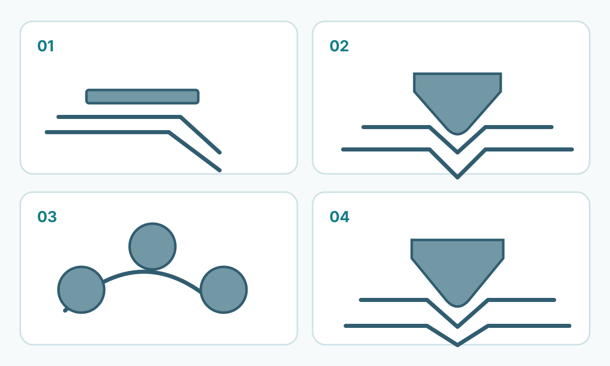
1. Confirm the material before choosing the bend setup
Start with grade, delivery condition and actual thickness. Low-carbon sheet, high-strength steel, stainless and aluminum can require different bend radii and forces even at similar thickness. Galvanized, prepainted or polished surfaces also add surface-protection requirements.
Settings from another material should not be transferred only because the nominal gauge looks similar. Confirm actual thickness and use the mill or supplier bendability guidance where available.
2. Check rolling direction
Rolling can create directional differences in sheet products. Many rolled steels show different bendability when the bend line is parallel versus perpendicular to rolling direction. Product-specific recommendations should decide the preferred orientation, especially for tight bends or higher-strength material.
When a drawing fixes grain direction for appearance, strength or forming sequence, that requirement becomes part of the bend plan.
3. Select an inside radius the material can tolerate
A tighter radius increases strain at the outside surface. Cracking risk rises when the radius is too small for the grade, thickness, edge condition and rolling direction. Higher-strength material often needs a larger minimum radius than mild sheet.
Avoid one universal radius-to-thickness rule. Use grade-specific bendability data and distinguish punch radius from the final inside radius of an air-bent part.
4. Match die opening and punch to the process
Air bending supports the sheet at the die shoulders while the punch controls depth. The final radius and angle depend on material and tooling geometry. Changing the V opening also changes force demand, flange requirements and bend geometry.
Bottoming uses a different contact condition near the final angle and should be treated as its own validated process. Tooling supplier charts and machine ratings are the proper sources for allowable load.
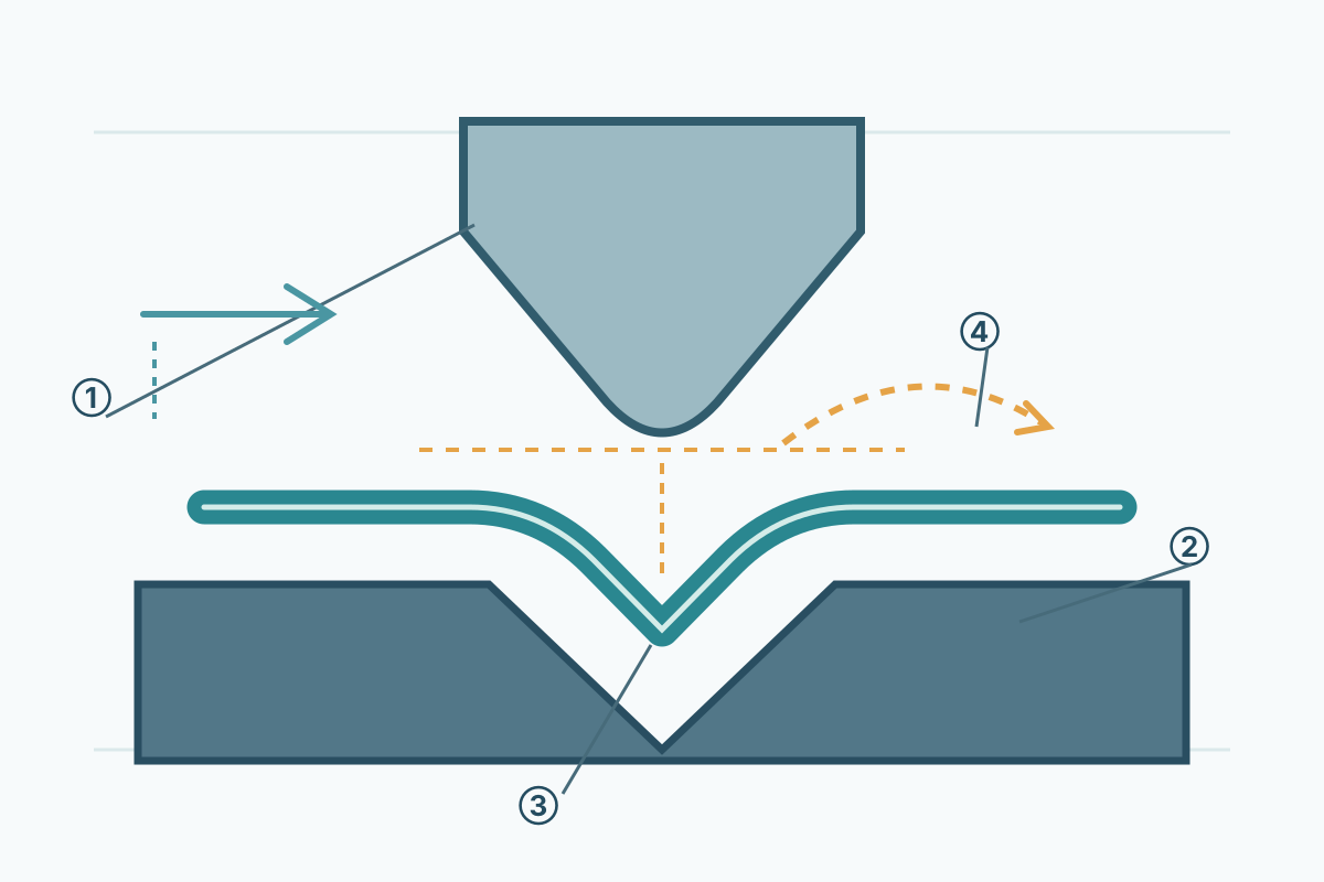
5. Use a validated bend allowance for the flat pattern
Material is redistributed through the bend region, so a flat blank cannot be derived by simply adding finished outside flange dimensions. Shops normally use bend allowance, bend deduction or CAD/CAM sheet-metal rules with a validated K-factor or bend table.
K-factor is setup-dependent. Use values proven for the material, thickness, radius and tooling, then verify the first part before production.
6. Plan for springback
Elastic recovery changes the final angle after forming. Material strength, thickness, radius, angle and forming method all affect the result. Measured first-piece results or validated software provide a better basis for compensation than a fixed universal value.
7. Protect visible surfaces and coatings
Polished, galvanized and prepainted sheet can be marked by debris, sliding contact or concentrated pressure. Tooling cleanliness, burr orientation and compatible surface-protection methods should be considered when appearance is specified.
Tight forming can strain metallic or organic coatings. Where coating cracking or appearance is critical, use the material or coating supplier’s forming guidance and qualify representative stock.
8. Check flange clearance and forming sequence
Return flanges, hems, boxes and nearby bends can create tool-access or collision constraints. Multi-bend parts should be reviewed as a complete forming sequence so a correct early bend does not block a later operation.
9. Verify machine and tooling capacity
Required forming force varies with material strength, thickness, bend length, die opening and process. Machine and tooling ratings, together with manufacturer force charts or validated calculators, set the allowable operating range.
Safety
Press brakes have a serious point-of-operation hazard. Guarding, sensing systems, work support and operating procedures must follow the machine manufacturer and applicable workplace rules. Large sheets can also move during forming, so handling and support requirements belong in the job plan.
A part that cannot be formed within the approved safe setup requires a different qualified setup or process.
First-piece checklist
Before production, verify material grade and thickness, rolling direction where relevant, inside radius and angle, tooling identification, capacity limits, flange clearance, flat-pattern rule, springback compensation, surface protection, and the required safety controls.
Measure the first part at the drawing’s specified locations and record the validated setup values for repeat work.
Practical takeaway
Sheet-metal bending is a matched system of material, geometry, tooling and machine capacity. Reliable results come from grade-specific bendability data, a validated flat pattern, first-piece verification and a controlled safe setup. Generic bend-radius or force shortcuts cannot replace actual material and tooling data.