
There is no single steel sheet thickness that is “right” for an enclosure, bracket, panel, guard or cover.
Start with what the part has to do. Define the load, unsupported span, acceptable deflection, geometry and environment. Then select a material and preliminary thickness, check forming and fabrication limits, account for thickness tolerance and available stock, and finally validate the part.
Use actual thickness in millimetres or inches for engineering decisions. Convert to a gauge designation only when you need to match a material-specific gauge system or available stock.
For the distinction behind the designation, read gauge number versus physical thickness .
If you only need to convert a gauge number to thickness, use the Sheet Metal Gauge Thickness Chart . This guide addresses the more difficult question: how thick should the sheet be in the first place?
Start with the part, not the gauge
Two parts made from the same 1.0 mm steel can behave very differently.
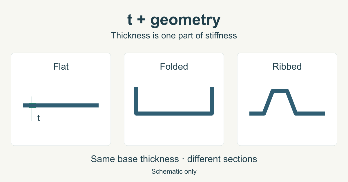
A small panel supported along four edges may be quite rigid. A much larger flat panel of the same material may flex or vibrate. Add a return flange, bead, rib or formed profile and the stiffness changes again without changing the base-metal thickness.
This is why a table that assigns one thickness to every “cabinet,” “bracket” or “machine guard” is only a rough fabrication reference. Thickness has to be considered together with geometry and support conditions.
Before choosing a number, define these requirements:
| Design question | Why it matters |
|---|---|
| What does the part do? | A cosmetic cover, pressure panel and load-bearing bracket fail in different ways. |
| Where is it supported? | Unsupported span strongly affects deflection and vibration. |
| What loads act on it? | Distributed load, point load, impact and cyclic loading require different checks. |
| How much deflection is acceptable? | A part can remain below yield strength and still be too flexible in service. |
| Will it be bent or formed? | Thickness, grade, bend orientation and tooling affect manufacturability. |
| How will it be joined? | Welding, fasteners, clinching and other joints impose different local requirements. |
| Is it exposed to corrosion? | Material and coating selection may be more effective than simply adding metal thickness. |
Scroll within the table to see all columns →
For safety-critical, structural, pressure-containing or regulated components, final thickness should follow the applicable design code, product standard and engineering calculation rather than a general-purpose web guide.
Thickness changes bending stiffness much faster than weight
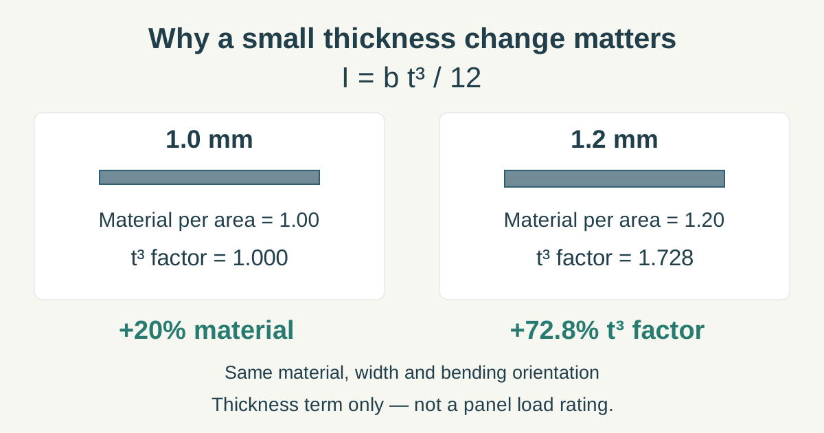
For a simple rectangular strip, the second moment of area about its centroidal axis is:
I = b × t³ / 12
where b is the strip width and t is its thickness.
For the same material and width, elastic bending rigidity therefore contains a t³ term. Classical plate theory likewise expresses plate bending rigidity with thickness cubed. See the technical source notes for the mechanics and forming references.
That cubic relationship is useful when screening alternatives:
| Thickness relative to 1.0 | Relative material per unit area | Relative t³ factor |
|---|---|---|
| 0.8 | 0.80 | 0.512 |
| 1.0 | 1.00 | 1.000 |
| 1.2 | 1.20 | 1.728 |
| 1.5 | 1.50 | 3.375 |
Scroll within the table to see all columns →
Changing a flat strip from 1.0 mm to 1.2 mm adds 20% to its material per unit area, while the thickness term in bending rigidity increases by about 72.8%.
That does not mean every 1.2 mm panel will deflect 72.8% less than a 1.0 mm panel. Real panels depend on width, length, support conditions, shape, load distribution and plate action. The comparison shows why relatively small thickness changes can have a large effect on bending behaviour—and why geometry must be considered at the same time.
The comparison above isolates the thickness term. It is a mechanics comparison, not a panel load rating.
Strength and stiffness are different design checks
A common mistake is to select a higher-strength grade and assume that a sheet of the same thickness will automatically become much stiffer.
Higher yield strength allows the material to sustain higher stress before permanent deformation. Elastic stiffness is a different property. For steel grades, Young’s modulus is broadly similar, so changing yield strength without changing geometry does not produce a comparable increase in elastic stiffness.
This matters when lightweighting a component. A higher-strength steel may allow the thickness to be reduced while still meeting a strength check, but the thinner section can become more flexible or more sensitive to buckling. Strength, stiffness and stability therefore need separate checks.
For a large cover or enclosure panel, excessive deflection or vibration may govern before the material approaches its yield strength. For a compact loaded bracket, strength around bends, holes and connections may be more important.
Geometry can be more efficient than adding thickness
Thickness is only one way to make a sheet-metal component stiffer.
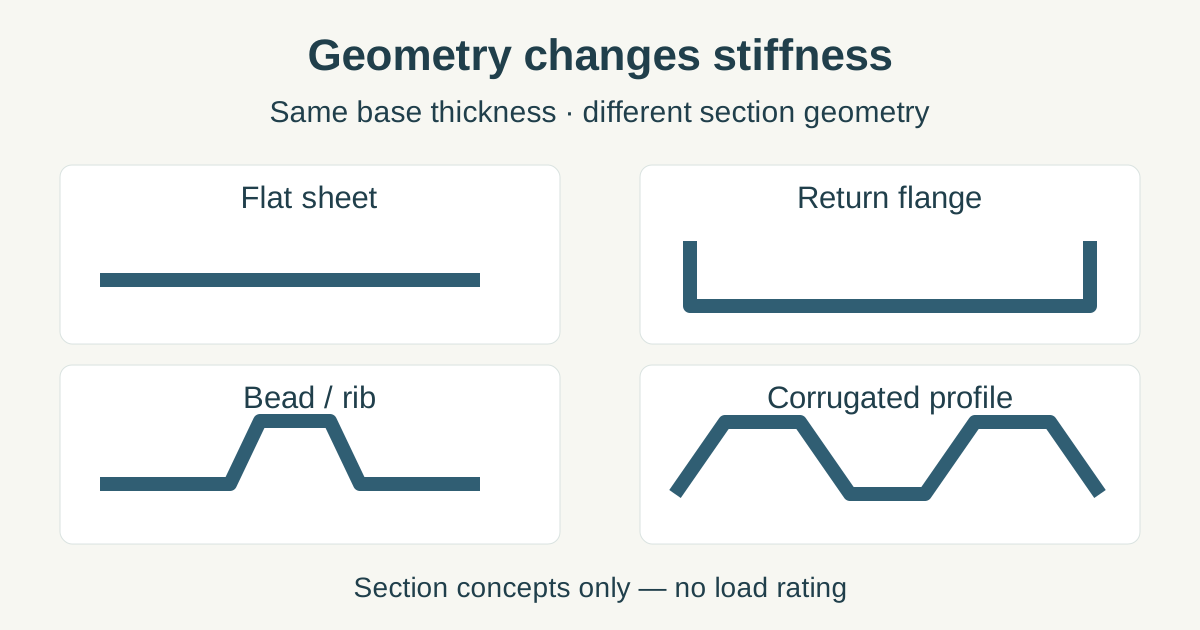
A return flange moves material away from the original flat plane. Beads and ribs change the local cross-section. A corrugated or trapezoidal profile creates a much deeper section. Adding an intermediate support reduces the unsupported span.
These changes can provide stiffness without increasing the thickness across the entire sheet.
This is especially important when a flat panel feels too flexible. Before simply moving to the next thicker material, compare the following design changes:
| Design change | What it changes |
|---|---|
| Return flange | Increases section depth around an edge |
| Rib or bead | Adds local geometric stiffness |
| Hat section or formed channel | Creates a deeper structural section |
| Additional fixing point | Reduces unsupported span |
| Corrugated or trapezoidal profile | Replaces a flat section with a formed section |
Scroll within the table to see all columns →
This principle is already visible in corrugated steel sheet : profiling changes the cross-section and stiffness even though the base steel itself does not become thicker.
Forming may set the practical thickness limit
A thickness that works in a strength calculation still has to be manufactured.
For press-brake bending, the required setup depends on the steel grade, material thickness, bend direction, punch radius, die geometry and available force. Minimum recommended radii can also vary with material and orientation.
For a real part, confirm the proposed thickness against the actual manufacturing route.
Bending
Check the material-specific minimum radius, die opening, flange geometry, springback and press capacity.
Cutting and punching
Confirm that the selected thickness is within the machine’s process window and that small holes, slots and edge details remain practical.
Welding
Joint design and heat input change as sheet becomes thinner or thicker. Thin material can be more sensitive to distortion; thicker material can require greater heat input and different joint preparation.
Fastening
Screw engagement, thread formation, rivets, clinch hardware and local bearing around holes may impose their own minimum material requirements.
The manufacturing supplier should therefore review the grade and thickness together, rather than approving a gauge number in isolation.
Coated sheet needs a clearly defined thickness basis
Galvanized, Galvalume and prepainted steel introduce another question: what does the specified thickness include?
Base-metal thickness and total coated thickness are not interchangeable concepts. Metallic coating and paint add layers to the steel substrate, while different product standards define measurement and acceptance in their own way.
For design and procurement, record the thickness basis required by the applicable product specification. Do not infer base-metal thickness from a single measurement on a finished coated surface.
For more detail, see Steel Sheet & Plate and the relevant coated-steel material pages.
Nominal thickness is not minimum delivered thickness
A design may call for 1.0 mm material, but the purchased product is supplied under a dimensional tolerance.
The applicable product specification, thickness range, width and ordering conditions determine the permissible variation.
ASTM A568/A568M , for example, provides general requirements for applicable hot-rolled and cold-rolled steel sheet, while the individual product specification remains part of the complete requirement.
This leads to an important design rule:
Do not make a critical calculation with nominal thickness and then assume every delivered sheet will equal that exact number.
Where a minimum steel thickness matters, determine which tolerance and measurement basis apply and use the appropriate design value.
After choosing a preliminary thickness, check how nominal thickness and the permitted delivered range are defined.
A practical thickness-selection workflow
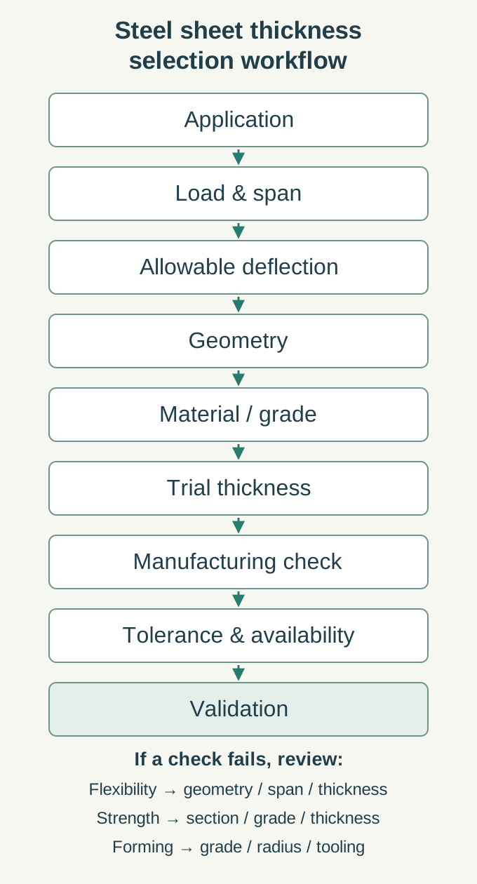
A good selection process narrows the problem in stages:
| Stage | Decision | Result |
|---|---|---|
| Function | Define load, impact, appearance, vibration and environment | Performance requirements |
| Geometry | Define panel dimensions, unsupported spans, folds, ribs and supports | Structural form |
| Material | Select steel family and candidate grade | Strength, stiffness and formability data |
| Preliminary thickness | Calculate or estimate a workable section | Trial thickness |
| Manufacturability | Check bending, cutting, welding and fastening | Manufacturable thickness |
| Supply | Check standard, tolerance and available stock | Purchasable specification |
| Validation | Review calculation, prototype, simulation or test as appropriate | Released design |
Scroll within the table to see all columns →
If the first trial is too flexible, compare a thicker sheet with a geometry change or shorter unsupported span.
If the first trial fails a strength requirement, consider both section geometry and material strength.
If the proposed material is difficult to form, changing the steel grade may be better than changing thickness alone.
Three common examples
Large enclosure panel
The first question is usually not “Should this be 1.0 or 1.2 mm?”
Start with panel dimensions, edge supports, door or hardware loads, allowable deflection and vibration. A return flange, internal rail or bead may change the result substantially. The final thickness can then be checked against forming, welding and surface-quality requirements.
Bent mounting bracket
A bracket introduces local bending, holes, fasteners and often a short load path. Check material strength and deformation first, then verify that the selected grade and thickness can achieve the required bend radius using available tooling.
Using a stronger grade may improve the strength margin, but stiffness and bendability remain separate checks.
Profiled roof or wall sheet
Choose roofing thickness from the finished profile system rather than from a generic flat-sheet table. The finished profile, support spacing, design loads, fastener system and base-metal thickness work together.
Use the named profile’s tested or engineered span/load information together with the applicable building requirements. The corrugated steel sheet guide explains the distinction between base-metal thickness, profile geometry and effective cover width. For a roof-specific decision, use the metal roofing thickness guide , where profile, purlin spacing, wind uplift and fastening are considered together.
Convert to gauge only after the thickness is known
Gauge is useful for communication and stock lookup, but it is a poor starting point for an engineering decision because gauge systems are material-specific.
First determine the required actual thickness and material. Then use the Sheet Metal Gauge Thickness Chart when a gauge designation is needed.
For material quantity and weight, enter the selected actual thickness in the Steel Plate & Sheet Weight Calculator .
Final check before releasing the thickness
A selected thickness is ready for a drawing or purchase specification only when the part has been checked as a complete system:
- material grade
- actual thickness basis
- load and span
- section geometry
- allowable deformation
- manufacturing process
- environmental protection
- dimensional tolerance
For simple non-critical parts, that review may be straightforward. For structural or safety-related components, it becomes an engineering design task governed by the applicable code and product standard.
The useful question is:
“What combination of material, thickness, geometry and support satisfies the required performance and can be manufactured consistently?”
Once thickness has been selected, convert it into the full purchase specification using How to Specify Steel Sheet and Coil Correctly .
FAQ
What is the best steel sheet thickness for a general enclosure?
There is no universal enclosure thickness. Panel size, unsupported span, folds, mounting points, hardware, vibration and acceptable deflection can change the requirement substantially. Establish those conditions first, then compare a trial thickness with possible stiffening features.
Is thicker steel always stronger?
For the same material and geometry, increasing thickness generally increases section capacity and stiffness. A finished part also depends on its grade, shape, support conditions, connections and failure mode. A properly stiffened thinner section can behave very differently from a flat sheet.
Does high-strength steel allow thinner sheet?
It can when material strength is the controlling requirement. Reducing thickness also reduces section stiffness and can increase sensitivity to deflection or instability. Strength and stiffness therefore need separate checks.
How much stiffer is 1.2 mm steel than 1.0 mm steel?
For a simple comparison with identical material, width and bending orientation, the thickness-cubed term rises from 1.0³ to 1.2³, or from 1.000 to 1.728. That is about a 72.8% increase in this geometric bending factor. Actual panel deflection still depends on dimensions, supports and load conditions.
Should I specify steel sheet in gauge or millimetres?
Use actual thickness in millimetres or inches for engineering and purchasing requirements whenever possible. If the market uses gauge, state the material and confirm its corresponding nominal thickness because the same gauge number can represent different thicknesses for different materials.