
Control sheet-metal welding distortion before the first arc: specify only the weld the design needs, maintain a consistent fit-up, distribute welding around the assembly and use a repeatable fixture. Confirm the result after the part has cooled and the clamps have been released. A panel that looks flat on the welding table can still move when removed.
This guide addresses dimensional control in welded steel-sheet assemblies. Process and filler selection belong in the stainless-steel welding guide ; the thin-sheet joining guide covers choosing between welded and mechanical joints. No single current, tack spacing or cooling time is suitable for every thin sheet.
1. Identify the movement and the acceptance condition
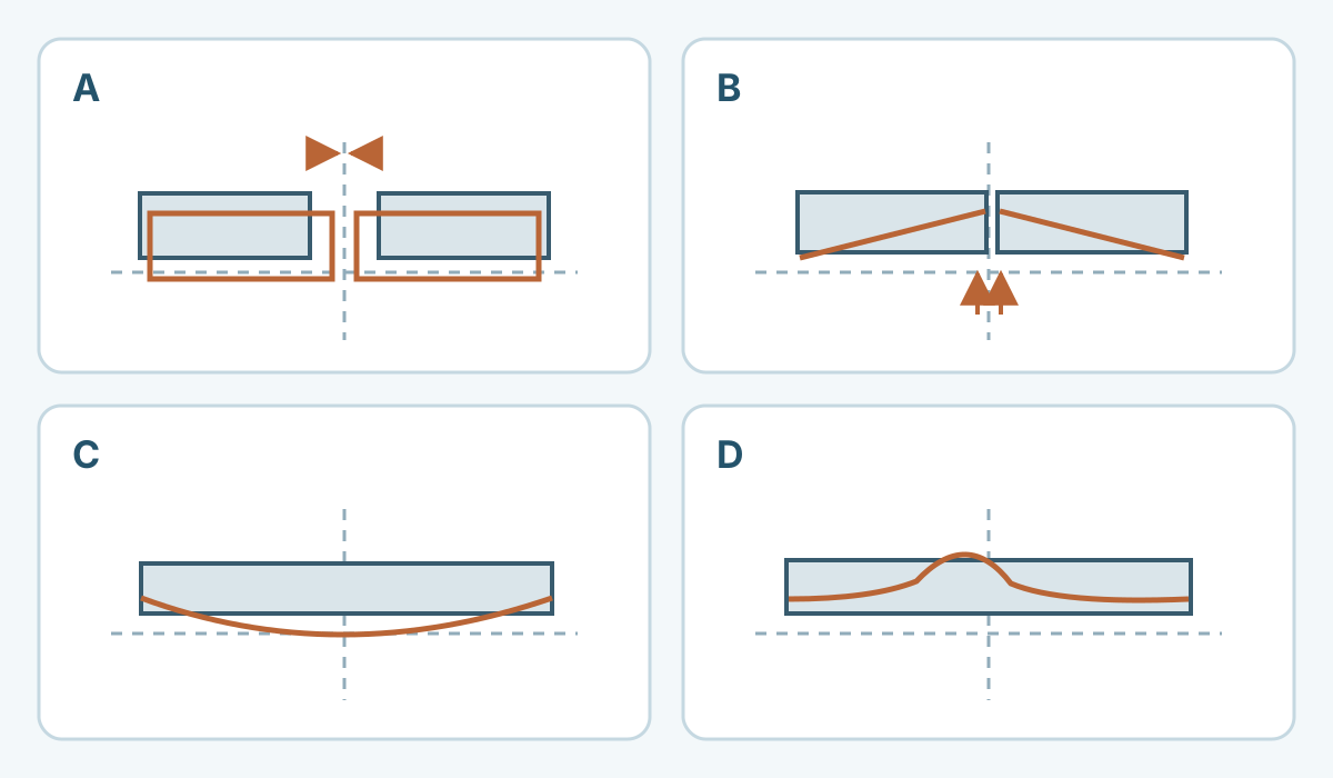
Welding heats a narrow region while the surrounding sheet remains cooler. Uneven expansion, contraction and local plastic strain can change the finished geometry. Long, lightly supported panels require particular attention to out-of-plane movement. TWI describes the underlying distortion mechanisms .
| Movement | Useful observation | First item to investigate |
|---|---|---|
| Transverse shrinkage | Joint closes or overall width decreases | Fit-up, tack sequence and deposited weld volume |
| Longitudinal shrinkage or bowing | Length changes or an edge develops a smooth curve | Long welds positioned away from the assembly's neutral axis |
| Angular distortion | Faces rotate across a seam | Uneven contraction through the thickness and one-sided welding |
| Buckling or local waviness | A broad panel develops unstable waves | Panel stiffness, thermal distribution and initial flatness |
| Twist | Corners no longer lie in the intended plane | Asymmetric sequence, fit-up and fixture support |
Scroll within the table to see all columns →
Record the initial shape before welding. Cutting, levelling, bending and handling may already have changed the blank; the cutting guide helps identify upstream influences. Mark the datums, measuring locations, support condition and permitted tolerances on the inspection plan. Flatness, flange angle and hole alignment are separate requirements. A straightedge check at selected locations is a useful shop comparison, but it does not automatically constitute a complete drawing-based flatness inspection.
2. Reduce avoidable welding and stabilize the joint
Check weld length, location, size and penetration requirements with the drawing and welding procedure specification (WPS). Excess weld metal adds shrinkage without necessarily improving the design. Ask the designer to assess seam length, distance from the neutral axis and balanced placement of required welds. TWI’s design guidance explains these controls.
Obtain design approval before changing weld size, replacing a continuous seam with intermittent welds or adding stiffeners. Load transfer, fatigue, leakage, hygiene and corrosion details can require a continuous joint. A skip sequence describes the order of depositing welds; the final seam may still need to be continuous.
Verify actual grade, thickness and coating, then prepare uniform edges and the specified joint gap. Record decimal millimetres or inches rather than relying on gauge alone. If the gap varies, correct the fit-up before welding. Filling an avoidable gap can alter weld volume and the thermal cycle. Keep material support and the orientation of formed flanges consistent between the trial and production parts.
3. Plan tacks, fixture restraint and release
Place tacks to hold alignment and the required gap through the assembly sequence. Determine their spacing, length and order through representative trials and the applicable procedure. Inspect tacks for defects; incorporated tacks need acceptable fusion and preparation. Follow the approved removal method for temporary attachments.
Support the sheet close enough to the joint to control movement while leaving torch, shielding and inspection access. Locate clamps so the part can be removed safely. Use the same locating points and release sequence in each trial. Excessive restraint can increase residual stress and cracking risk in susceptible materials, as explained in TWI’s restraint guidance .
Pre-setting can compensate for a repeatable movement. Establish it using assemblies representative of the actual panel size and stiffness. Record the starting offset and final released shape; a successful small coupon alone does not establish compensation for a wide panel. Review any pre-bend for effects on fit-up, surface finish and assembly access.
4. Manage heat and the order of welding
Work within a validated WPS that achieves the specified fusion and penetration with controlled deposition and travel. Reducing current alone may create a slow, poorly fused weld. Keep the weld pool and bead within the qualified process window. Follow material-specific preheat and interpass requirements; the smallest possible heat input is not a universal metallurgical target.
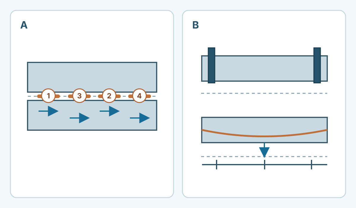
For long seams, test short runs distributed around the assembly. Back-step welding deposits each short run opposite to the overall progression. Skip welding places separated runs in a planned order and fills the remaining sections when a continuous seam is required. Alternate required welds across the assembly where access and procedure allow. TWI covers these sequence principles . Validate starts, stops and overlaps as part of weld quality.
A compatible backing or chill bar can help extract heat and support a thin-sheet weld. Its contact, cleanliness and effect on penetration belong in the trial; prevent backing material entering the weld. Miller discusses thin-sheet fit-up and backing . Do not add uncontrolled water quenching, compressed-air cooling or a wet rag to an established procedure.
When comparing trials, record travel speed, voltage, current or equipment energy data, deposited length and temperature checks. Arc energy and net heat input have different meanings; use the method required by the governing procedure and the equipment’s waveform. A pulse setting or an average-current display alone cannot rank two procedures reliably. Austenitic stainless sheet also needs grade-specific thermal control; AWS discusses its distortion tendency .
TWI explains the energy definitions and parameter measurement .
5. Run a first-off trial with traceable measurements
Use a representative assembly with production material, edge preparation, joint length and supports. Agree dimensional and weld-quality acceptance before the trial. Preserve the approved settings while changing one controllable variable at a time, such as sequence or clamp location. Repeat the trial to establish consistent acceptance.
Dimensional acceptance does not establish weld integrity. Check fusion, penetration and any required leak or mechanical tests separately under the applicable specification.
| Checkpoint | Record | Decision |
|---|---|---|
| Before tacking | Grade, thickness, blank shape, gap and datum setup | Correct incoming or fit-up errors |
| After tacking | Gap, alignment, tack condition and clamping | Confirm a stable starting assembly |
| After welding and cooling in the fixture | Temperature condition, shape and weld inspection | Check compliance and controlled release readiness |
| After fixture release | Dimensions at the same datums and defined supports | Accept, adjust the trial plan or hold for review |
Scroll within the table to see all columns →
For a tray with four corner seams, label the corners and record flange angles and diagonals before tacking. Compare an approved sequence that alternates separated corners with the baseline process, keeping weld requirements and fixture conditions constant. Measure again after the same cooling and release conditions. This is a trial design, with no claimed test result or universal preferred order. Check later finishing operations if they are part of the dimensional acceptance state.
6. Diagnose failures before releasing the process
If the joint closes during tacking, inspect the starting gap, tack order and support. If the panel moves mainly after unclamping, investigate restraint and residual movement. If each successive part worsens, check fixture heating, contact, actual settings and material variation. Photograph and measure the same locations to distinguish repeatable bias from random variation.
Hold parts outside tolerance. Mechanical or thermal straightening needs a controlled repair method, appropriate material limits and renewed inspection. TWI identifies metallurgical and over-shrinkage risks in thermal correction . Do not improvise a flame pattern or quench cycle for thin, coated, high-strength or stainless sheet.
Release production with a recorded weld map, WPS, tack and clamp plan, temperature checks, cooling/release condition, inspection method and revalidation triggers. Control fumes, hot surfaces, sharp edges and stored fixture forces. See the galvanized-steel welding guide for coating-related precautions. The HSE fume guidance is a UK reference; apply the workplace requirements governing the job.