
Plasma cutting uses an electrically conductive plasma arc to melt and expel material from the cut. For steel work, usable thickness and edge quality depend on the complete system: power source, torch, consumables, gas, material, amperage, cut speed, torch height and machine motion.
Start with the manufacturer’s current cut chart for the exact torch, consumables, material and thickness. Published “maximum thickness” numbers from another system are not process settings.
Thickness: use the system cut chart
Separate three ideas: a standard’s dimensional scope, a machine’s rated capability and the quality required by the drawing. ISO 9013:2017 covers geometrical specifications for plasma cuts from 0.5 to 150 mm within its stated scope. That range does not mean every plasma system can cut every thickness to the same quality.
Use the equipment manual to identify recommended cut settings and any slower maximum or severance capability. If the drawing requires a defined cut-quality class, reference the applicable acceptance standard or project criteria explicitly.
The variables that control cut quality
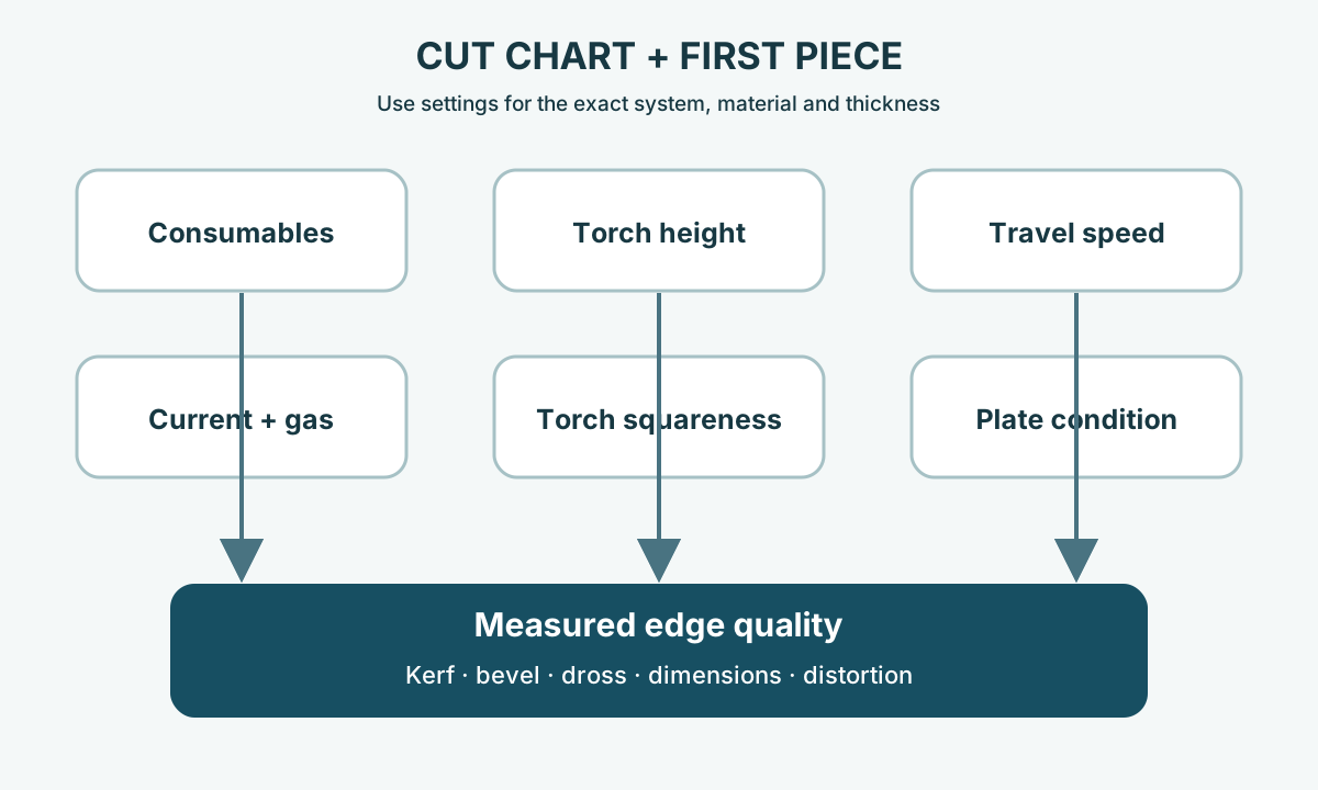
Consumable condition, torch squareness, torch-to-work distance, amperage/gas selection and travel speed interact. Worn consumables can move the arc and degrade edge consistency. A torch that is not square can create an angle error that resembles a process-setting problem.
Speed and dross
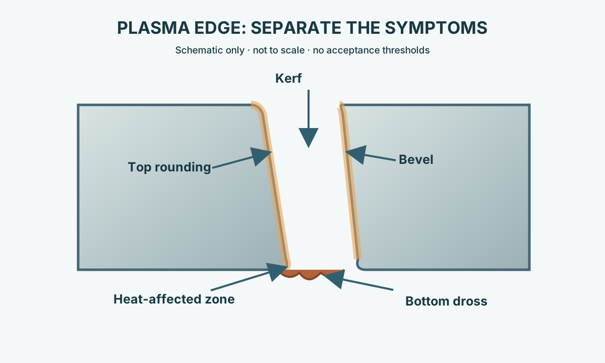
Dross is resolidified material attached to the bottom edge. Hypertherm distinguishes low-speed and high-speed dross because opposite speed errors can produce different deposits. Diagnose the whole setup before changing one parameter. Low-speed dross usually reflects excessive energy per unit length at the edge, while high-speed dross forms when the arc trails and fails to clear the kerf cleanly. The same symptom can also be influenced by torch height, amperage, gas delivery, consumable wear and plate condition. Return to the cut chart, confirm the complete setup, and change one approved variable at a time.
Bevel, kerf and torch height
Plasma edges normally have some angularity because the arc and gas jet are constricted through the torch. Excessive bevel can also indicate a setup problem. Hypertherm lists torch standoff, cut speed, current, nozzle condition and torch squareness among the variables that affect angularity.
For mechanized cutting, torch-height control uses the system’s prescribed pierce height, cut height or arc-voltage settings to keep the torch at the intended distance from the workpiece. A height error can change top-edge rounding, kerf shape, bevel and consumable life. Use the values for the exact system and consumables; generic voltage or standoff numbers are unsuitable substitutes.
Kerf width also changes with process, current, speed, material and consumables. CNC compensation should be based on a validated first piece. Measure the finished part rather than assuming a nominal kerf from another machine.
Heat input, heat-affected zone and distortion
Plasma is a thermal process, so the cut edge experiences a heat-affected zone. Its width and metallurgical effect depend on material, thickness, process power, gas, speed, cut sequence and the specific plasma system. A single universal HAZ width should not be used for design or acceptance.
Slower travel, repeated nearby cuts and dense nesting can increase local heat accumulation. Thin sheet and long narrow parts can move as stresses are released. Use the qualified cut chart, stable support and a cut sequence that limits unnecessary heat concentration. Where edge hardness, weldability, fatigue performance or a later forming operation is critical, qualify the cut condition on representative material and define any required edge preparation.
Distortion belongs in the acceptance plan. Check flatness, bow, local lift and dimensional shift after the part has cooled to the inspection condition specified for the job.
Material condition, coatings and operator protection
Plasma cutting requires an electrically conductive workpiece and a stable electrical return path. Carbon steel, stainless steel and aluminium can all be plasma-cut with suitable equipment, gases and consumables, although the correct process window differs by material.
Surface condition matters. Heavy scale, coatings, paint, galvanizing residues, oil and contamination can change arc behaviour, edge appearance and the fumes released during cutting. The cutting procedure should identify the actual material and coating system before production.
Thermal cutting can generate metal fumes, gases, ultraviolet radiation, hot particles, noise and electrical hazards. Ventilation and exposure controls must match the material, coating and workplace. OSHA’s US rules require welding and cutting ventilation sufficient to control hazardous fumes and gases; other jurisdictions have their own requirements. Follow the machine manual, site risk assessment and locally applicable safety rules.
Inspect a representative first piece
A production-ready plasma program needs more than a successful arc start. Inspect a coupon or first part made with the production material, thickness, consumables and motion settings.
Check:
- overall dimensions, hole size and feature position;
- edge angularity and whether the required side of the cut has the better edge;
- kerf compensation and corner or small-feature accuracy;
- dross type and removability;
- top-edge rounding, surface roughness and drag-line consistency;
- visible thermal distortion and flatness;
- cut-edge condition where welding, coating, machining or forming follows;
- pierce condition and any damage close to the finished contour.
| Observed symptom | Checks before an approved adjustment |
|---|---|
| Heavy, easily removed bottom dross | Cut speed, torch height, current/nozzle choice and heat input against the cut chart |
| Hard bead of bottom dross with trailing arc marks | Excessive speed, penetration, current/nozzle choice and torch height |
| Excessive positive bevel or top rounding | Torch height, worn nozzle, amperage, speed and torch squareness |
| Bevel changes around the contour | Torch squareness, cut direction, consumable condition and machine motion |
| Thin part lifts or bows | Heat concentration, nesting, support, cut sequence and released residual stress |
Scroll within the table to see all columns →
Treat the table as a diagnostic starting point. The manufacturer’s troubleshooting procedure and the measured part decide the next approved adjustment.
A practical setup and release sequence
- Confirm the drawing, material grade, thickness, coating and required edge/tolerance class.
- Select a plasma system with appropriate recommended cutting and piercing capability for that material and thickness.
- Load the manufacturer’s cut chart for the exact torch, consumables, gas/process and amperage.
- Verify consumable condition, torch squareness, work connection, gas supply and machine motion.
- Apply the prescribed pierce height and delay, cut height or arc-voltage target, and travel speed.
- Cut a representative first piece and measure dimensions, bevel, dross, kerf compensation and distortion.
- If correction is needed, change one approved variable at a time and cut another sample.
- Record the released setup, consumable set, inspection results and the trigger for requalification.
For the earlier process-selection decision, compare plasma with the other options in How to Cut Sheet Metal . Where laser is a realistic alternative, Laser Cutting Steel Sheet covers its separate process and edge-quality considerations.