
A reliable flat pattern needs a defined bend geometry and a bend model that matches the actual process. Bend allowance (BA), bend deduction (BD), outside setback (OSSB), and K-factor describe different parts of that calculation. Mixing their dimension conventions is a common source of flat-length errors.
K-factor is most useful as a calibrated production input. Start with a geometric estimate, form a coupon with the real material and tooling, measure the result, and feed the verified value into CAD or a bend table.
1. Define the quantities before calculating
| Symbol | Meaning | Use |
|---|---|---|
| T | Sheet thickness | Use the actual or specified thickness basis for the job. |
| R | Finished inside bend radius | Keep it distinct from punch-tip radius unless the qualified setup makes them equivalent. |
| A | Bend angle swept by the material | For this article, flat is 0° and a right-angle bend uses A = 90°. |
| K | Neutral-axis offset ratio t/T | Locates the neutral axis through the thickness for the unfolding model. |
| BA | Arc length along the neutral axis | Add it to tangent-length dimensions. |
| OSSB | Outside setback to the virtual sharp | Connects outside flange dimensions to the bend region. |
| BD | Bend deduction | Subtract it from outside virtual-sharp flange dimensions. |
Scroll within the table to see all columns →
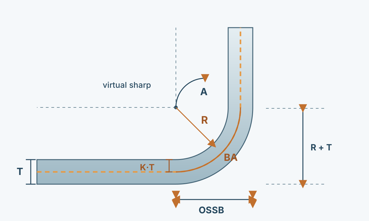
2. Lock the angle convention
In the formulas below, A is the angle through which the sheet is bent. A flat sheet begins at 0°. A finished 90° corner uses A = 90°. Some drawings and CAD systems display the included or open angle instead, so convert that value before using the equations.
This check matters most on acute and obtuse bends. A correct K-factor combined with the wrong angle convention still produces the wrong flat length. Record the convention in the bend table or calculation note so programming and inspection use the same definition.
3. Calculate bend allowance from K-factor
SOLIDWORKS defines K as the neutral-axis distance from the inside face divided by sheet thickness. With A in radians:
BA = A × (R + K × T)
With A in degrees:
BA = π × (R + K × T) × A / 180
The term R + K × T is the neutral-axis radius used by this linear unfolding model. Autodesk Inventor uses the same linear form for its K-factor unfolding method.
K should not be treated as a universal material constant. The effective value used to hit production dimensions can change with grade and condition, thickness, bend radius, rolling direction, tooling, forming method and the way the finished bend is measured.
4. Use bend deduction with outside flange dimensions
Bend allowance works naturally with straight tangent lengths. Bend deduction is convenient when the drawing gives outside flange dimensions to the virtual sharp. SOLIDWORKS describes the two flat-length methods as:
Lflat = L1 + L2 + BA for tangent lengths
Lflat = O1 + O2 - BD for outside virtual-sharp dimensions
For a simple bend using the angle convention above, the geometric outside setback is:
OSSB = (R + T) × tan(A / 2)
and the corresponding deduction is:
BD = 2 × OSSB - BA
Keep the dimension scheme explicit. A tangent length and an outside virtual-sharp length are different inputs even when they appear on the same drawing.
5. Calibrate K-factor from a real bend
Use a coupon from the same material specification, thickness range and rolling orientation planned for production. Form it with the intended press-brake method, punch, die opening and target radius. Measure the finished angle, inside radius and flange dimensions after springback.
From the measured flat blank and finished outside flange dimensions, determine the effective bend deduction, then recover the bend allowance for that geometry. Rearranging the K-factor equation gives:
K = (BA / A - R) / T when A is in radians.
Repeat enough samples to expose normal variation. Store the result with the material, thickness, radius/tooling, angle range, machine/process and revision. A value calibrated on one setup should be revalidated when any of those inputs changes materially.
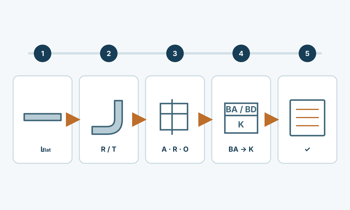
6. Worked 90-degree example
Assume T = 1.5 mm, R = 1.5 mm, K = 0.40, and A = 90°.
The neutral-axis radius is 1.5 + 0.40 × 1.5 = 2.1 mm. Bend allowance is:
BA = π/2 × 2.1 = 3.299 mm
Outside setback is:
OSSB = (1.5 + 1.5) × tan(45°) = 3.000 mm
Therefore:
BD = 2 × 3.000 - 3.299 = 2.701 mm
If the outside virtual-sharp flange dimensions are 40 mm and 60 mm, the calculated flat length is:
Lflat = 40 + 60 - 2.701 = 97.299 mm
This is a geometric starting point. Production accuracy comes from checking the actual bend and replacing the assumed K-factor with calibrated data where needed.
7. Build bend tables for production
A useful bend table separates variables that genuinely change the developed length. Typical keys include material/condition, nominal or actual thickness range, forming method, die opening, punch or achieved inside radius, bend angle, grain direction when relevant, and the verified K-factor or bend deduction.
Avoid forcing one K-factor across a wide thickness or radius range just to simplify the table. If a machine controller or CAD system supports measured bend tables, store the verified values directly when that better represents the process.
Revision control matters. When tooling is replaced, material source changes, or the press-brake method is revised, test the affected table region before carrying old compensation forward.
8. Flat-pattern handoff and common errors
Before releasing a flat pattern, verify the material and thickness basis, finished inside radius, bend angle convention, dimension scheme, tooling/process, rolling direction where relevant, and the bend-data revision. Keep units consistent through every formula.
The most common failures are practical: applying a K-factor from a different setup, reading an open angle as a bend angle, mixing outside and tangent dimensions, or changing the production radius without regenerating the flat pattern.
For radius selection, see How to Choose Sheet Metal Bend Radius . For the wider forming sequence, see How to Bend Sheet Metal .