
A bend radius should be selected from the actual material, thickness, direction and forming process. A value copied from another job can be too tight for the grade, unnecessarily large for the geometry, or incompatible with the available tooling.
The most useful question is the required finished inside radius, followed by the tooling and process needed to achieve it reliably. Material data sheets may also specify a minimum bend radius or a recommended punch radius. Those terms are related, yet they are not automatically interchangeable.
Quick bend-radius decision sequence
| Check | Why it matters | What to verify |
|---|---|---|
| Grade and condition | Strength, ductility and microstructure affect cracking and springback | Exact grade, delivery condition, heat treatment and supplier bendability data |
| Actual thickness | Outside-fiber strain rises as the radius becomes tighter relative to thickness | Measured or specified thickness range, not a gauge name alone |
| Rolling direction | Rolled sheet can have directional bendability | Bend line relative to rolling direction and grade-specific recommendation |
| Cut-edge condition | Damage, burrs and thermal effects can reduce edge ductility | Edge quality near the bend and any supplier-required preparation |
| Forming method | Air bending, bottoming and other methods create different contact and radius behavior | Process, die opening, punch radius, force and machine/tool limits |
| Finished part | Radius affects flange geometry, clearance, flat pattern, coating and downstream fit | Drawing radius, tolerance, bend allowance and assembly requirements |
Scroll within the table to see all columns →
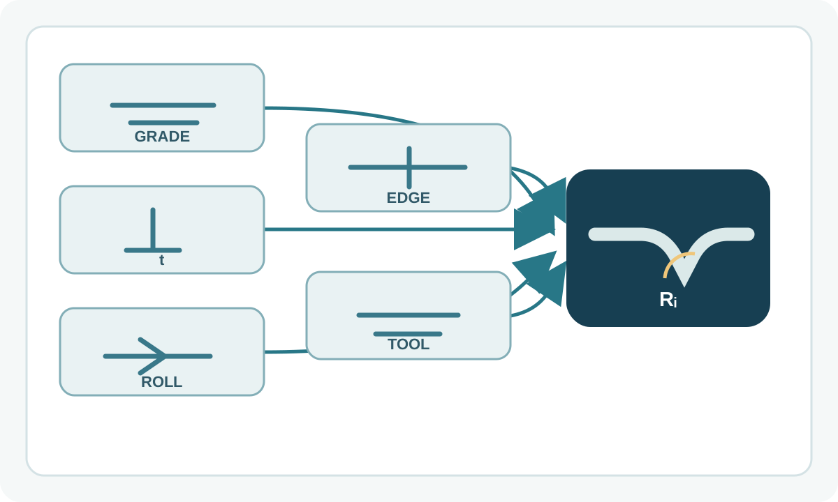
1. Start with the grade, condition and thickness
A universal radius-to-thickness ratio does not exist across all sheet metals. Low-carbon sheet, advanced/high-strength steel, stainless steel and heat-treated alloys can have very different bendability at the same nominal thickness.
Use the exact grade and delivery condition. Then find the producer’s bending recommendation for that product and thickness range. Where the producer publishes a guaranteed minimum final inside radius, treat it as a material limit for the stated conditions. Where only a recommended punch radius is given, do not relabel it as a guaranteed finished radius.
Actual thickness matters because bending strain depends strongly on the radius-to-thickness relationship. For production planning, work in millimetres or inches rather than relying only on gauge designations.
2. Distinguish finished inside radius from punch radius
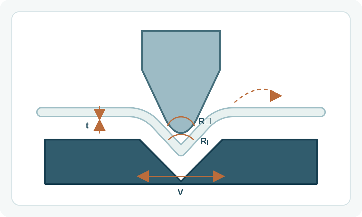
In press-brake work, several radii can appear in the same discussion:
- the punch-tip radius;
- the final inside radius in the part;
- a minimum bend radius published for the material;
- a test mandrel or former radius used in a bendability standard.
These numbers can coincide in a specific setup, but there is no general rule that makes them identical.
During air bending, the sheet is supported at the die shoulders and the final geometry depends on material response, punch geometry, die opening and penetration. A punch radius that is smaller than the finished radius can therefore be normal. Bottoming creates different contact conditions and needs its own validated tooling relationship.
3. Check rolling direction
Rolling creates directional microstructure and properties in many sheet products. The preferred bend orientation can therefore change the allowable radius.
Supplier recommendations often distinguish bends with the bend line transverse to the rolling direction from bends with the bend line parallel to it. For some high-strength steels, transverse bending is more favorable. That observation should stay grade-specific; it is not a universal rule for every steel product.
If a drawing fixes material direction, surface grain or a cosmetic orientation, include that constraint before finalizing the radius.
4. Treat the cut edge as part of the bending problem
A bend that intersects or starts near a cut edge may fail earlier when the edge contains a large burr, local cracking, hard heat-affected material or severe roughness.
Laser, plasma, shearing and punching create different edge conditions. Some steel producers specify edge grinding or a larger bend radius for particular grades and thermally cut edges. Apply those requirements only to the grades and processes for which they are published.
When the bend is critical, qualify the real cutting-plus-bending route rather than testing a polished laboratory edge that production will not reproduce.
5. Match the radius to the forming method and tooling
For air bending, die opening, punch radius, material strength and thickness all influence force, angle and final radius. A wider die opening generally reduces force demand but also changes the geometry and minimum flange requirement.
Tooling limits matter at both ends:
- a punch that is too sharp for the material can promote surface cracking or excessive thinning;
- a large punch may make a small specified inside radius impossible;
- a narrow die can raise force and local contact pressure;
- machine and tooling load ratings can rule out an otherwise geometrically attractive setup.
Use the press-brake and tooling manufacturer’s force charts or validated software for capacity. Avoid deriving a production force limit from a generic web formula when the machine and tool ratings are available.
6. Account for springback
After the load is removed, elastic recovery changes the angle and can slightly change the apparent radius. Springback generally becomes more significant as material strength increases and as the forming setup becomes more open relative to thickness.
Production control usually compensates through programmed overbend, tooling choice, measured first-piece correction or a validated material/tool database. The required compensation is setup-specific.
7. Check the drawing and downstream process
The radius should serve the finished component. Review:
- flange length and tool access;
- nearby holes, slots, hems and embossments;
- bend allowance or bend deduction used for the flat pattern;
- coating or polished-surface damage risk;
- weld fit-up and assembly clearance;
- fatigue or cyclic loading where relevant;
- cosmetic continuity across neighboring bends.
Changing the inside radius changes the developed flat length and can shift hole or flange positions. Update the flat pattern whenever the production radius changes materially.
8. Use bend-test standards for what they actually measure
ISO 7438:2020 specifies a bend-test method for metallic materials. It is useful for assessing whether a test piece can undergo specified plastic deformation under defined test conditions.
A bend-test standard does not supply one production bend radius for every fabricated part. Production selection still needs the actual grade, thickness, rolling direction, edge, tooling, geometry and applicable product specification.
A practical specification workflow
- Identify exact material grade, condition and thickness range.
- Read the producer’s bendability table or technical recommendation.
- Confirm whether the stated value is a finished inside radius, punch radius or test condition.
- Check bend-line direction relative to rolling direction.
- Review cut-edge preparation for the actual cutting process.
- Select press-brake process, punch and die opening within machine/tool ratings.
- Calculate the flat pattern with the intended radius and validated bend allowance.
- Form and inspect a first article before freezing production settings.
Practical takeaway
A reliable bend radius is a controlled combination of material capability and forming setup. Start with the producer’s grade-specific bendability data, define the finished inside radius clearly, and then validate direction, edge condition, tooling, springback and flat-pattern assumptions on the real process.
For the broader forming workflow, see How to Bend Sheet Metal . For material thickness selection, see How to Choose Steel Sheet Thickness .