
Cut-to-length processing converts steel coil into sheets or rectangular blanks by feeding the strip to a selected length and cutting across it. The finished width normally follows the incoming strip; slitting or side trimming must be included if a different width is needed. The line coordinates coil handling, length control, cutting and stacking; the installed leveling equipment determines the shape-correction step.
From coil to cut sheets
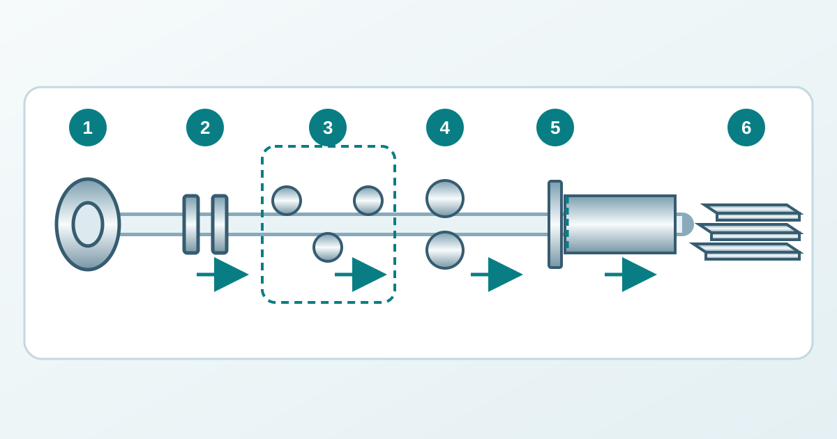
The uncoiler supports the coil and releases strip into the entry section. Guides establish its path. Entry equipment may open the coil, feed the leading end and crop damaged ends, depending on the installation.
Where roller leveling is installed, successive rolls bend the strip in alternating directions to improve shape. Its capability depends on the material, thickness, width and equipment design. Some lines use a different leveling arrangement or include further processing stages. The line measures and feeds strip for the required cut length; the sensing and feed equipment may be integrated with other units. A transverse shear separates the sheet, which transfers to the runout and stacking equipment. The length-control system coordinates material travel and cut timing.
How the line keeps material moving
With a stationary shear, strip at the cutting station stops for the cut. Where an accumulation loop is fitted, stored strip can buffer the difference between upstream travel and intermittent feeding at the shear. The loop has finite capacity, so its controls must keep the sections coordinated.
A flying shear synchronizes its travel with the moving strip during cutting. Rotary shears use a coordinated blade motion to cut while material continues moving. These arrangements describe cutting motion; their names alone do not establish a line’s accuracy, surface quality or output.
The feed cycle, shear and stacker all constrain output. Shorter sheets require more cuts per length of strip. Compare capacity at the actual material and sheet size; maximum strip speed alone cannot describe a job.
Four separate checks on the sheet
Length, squareness, flatness and surface condition need separate acceptance criteria. Passing one check leaves the others unresolved. Measure using the agreed product specification, support condition and inspection method.
| Characteristic | What it establishes | Process questions |
|---|---|---|
| Length | Distance between the cut ends at the specified measurement locations. | Are length sensing, feed motion and cut timing consistent? |
| Squareness | Relationship between the cut end and the longitudinal reference edge. | Are the strip path, reference edge and cutting alignment appropriate? |
| Flatness | Departure from the specified reference plane under the stated measurement conditions. | Are incoming shape and leveling capability compatible with the requirement? |
| Surface condition | Scratches, pressure marks and coating or finish damage. | Where does the first mark appear: entry, rolls, transfer or stacking? |
Scroll within the table to see all columns →

Burr and cut-edge condition also need their own requirements where relevant. These investigation points allow for several possible causes; appearance alone cannot identify a fault. Shear clearance and blade condition belong to the approved machine setup.
Why flat sheets can move after cutting
A sheet can look flat while retaining residual stresses. Cutting it into narrower or irregular parts changes the balance of those stresses, and the parts may distort. Laser or plasma cutting also introduces heat, which can contribute to the final shape.
Leveling can improve flatness and reduce residual stresses, with the result depending on the method, material and settings. Delivery flatness by itself cannot guarantee the shape of every downstream part. Where later cutting stability matters, agree a representative processing trial and acceptance criteria for that stage.
Stacking and traceability
The stacker receives each sheet, aligns the pack and supports its transfer. Contact surfaces, sliding between sheets and handling can affect a finish that passed through the cutting section intact. Surface-sensitive products may need specified protection and a suitable handling arrangement.
Keep the pack connected to its source coil and job record. Useful identifiers include the coil or heat reference, grade and condition, nominal dimensions, quantity, and inspection status. A pack label supports traceability and must remain linked to the applicable material certificate. The label alone cannot verify the grade or test results, and cutting does not provide new material-test evidence.
Scope and further reading
This article explains the integrated coil-to-sheet route. Product and supply requirements belong in steel sheet and plate ; longitudinal width division is covered in steel coil slitting . For guillotine setup and edge-quality controls, use the sheet-metal shearing guide .
Manufacturer descriptions show available arrangements. They provide no universal length tolerance, speed or blade-clearance setting. Operation, threading, blade work and coil handling require trained personnel and the line’s guarding and isolation procedures.