
Steel coil slitting divides a wide parent coil lengthwise into narrower strips and rewinds them as daughter coils. Width changes at the rotary knives; slitting does not intentionally reduce the bulk thickness, although deformation occurs at the cut edges. A slitting line coordinates feeding, cutting, strip separation and winding so that the new coils can feed the next operation.
From parent coil to narrow coils
The uncoiler releases the strip into the entry section. Guides establish its path toward the slitter. Threading and crop equipment vary with the installation; the leading end must travel through the line before normal production begins.
Pairs of circular knives on upper and lower arbors divide the moving strip. Spacers and the knife arrangement establish the cutting positions across its width. The plan may include edge trimming. Trim goes to a separate collection system, while the useful strands continue toward the recoiler. Separators keep neighbouring strands in their assigned lanes.
A loop and tension section can manage strip travel between cutting and winding. The recoiler winds the strands into daughter coils, which are secured and removed using the line’s handling system. Actual layouts vary with the line.

What the knives control
Lateral clearance and radial overlap describe different parts of the knife relationship. Clearance is the gap between opposing cutting edges across the strip width. Overlap describes their radial engagement. Neither is the finished strip width: width comes from the complete tooling stack and cutting positions.
Material thickness, strength, ductility and tool condition influence the cutting response. A successful setup for one coil cannot be transferred solely because the next coil has the same width. The process must be validated against the actual steel and approved tooling procedure. Knife clearance, tension and speed require line-specific settings.
Why winding needs its own controls
After cutting, several narrow strands must run together. Separation controls their lateral positions; tension controls the force along their travel. A separator cannot replace tension control. Equipment manufacturers offer different tensioning arrangements for different material and surface requirements.
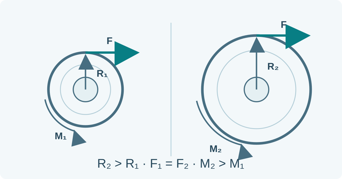
For an ideal winding strand, torque is the strip force multiplied by the effective winding radius. As the coil builds, the radius changes. This basic relationship explains why constant torque alone does not give constant strip tension throughout a coil; real drives also account for acceleration and mechanical losses.
For strands wound at a common angular speed, different effective winding radii demand different surface speeds. Incoming thickness variation and the way wraps build can therefore complicate multi-strand winding. The line’s compensation arrangement and validated settings matter. Increasing tension indiscriminately can damage material or surfaces.
Reading the result by process stage
| Observation | Process question |
|---|---|
| Width differs from the planned product | Were cutting positions, tooling and measurement conditions correct? |
| A strand wanders from its lane | Are strip guidance, separation and the incoming condition consistent? |
| Surface marking appears after a contact point | Are the contact surfaces clean and appropriate for the finish? |
| Winding becomes uneven | Are strand travel, tension and coil build compatible? |
Scroll within the table to see all columns →
These questions locate an investigation; they do not identify a cause from appearance alone. Product acceptance for burrs, edge condition, width and camber belongs in the steel-strip specification. A line may slit material successfully while a delivered coil still fails one of those requirements.
Slitting, leveling and cut-to-length
Slitting establishes narrower widths. Leveling addresses shape through a separate deformation operation. Cut-to-length divides strip transversely into sheets or blanks. Combined lines can include more than one of these functions, so the equipment list should state which operations actually occur.
A narrow coil does not automatically have a deburred edge, a guaranteed flatness or a changed temper. Those require their own specified process and acceptance conditions. A width-layout calculation likewise establishes geometry only; it cannot approve tooling, surface protection or winding quality.
Sources and scope
This is a process explanation for readers interpreting a coil-processing route. It is not an operator setup or maintenance procedure. Follow the particular line’s guarded operating and isolation procedures for threading, tool changes and coil handling. Manufacturer references establish available equipment functions; they do not establish universal tolerances or settings.
Steel-strip requirements · Coil-slitting layout calculator · Source notes