
Steel’s modulus of elasticity, usually written E or called Young’s modulus, describes the slope of its uniaxial stress–strain response in the linear-elastic range. A larger E gives less elastic strain at the same stress. Engineers often use a rounded value near 200 GPa for structural-steel calculations, but the governing design basis, grade and temperature determine the value to use.
200 GPa = 200,000 MPa = 200,000 N/mm² ≈ 29 million psi, or about 29,000 ksi. This is a modulus value, not a steel strength rating or a guaranteed property of every delivered steel.
Read E from stress and strain
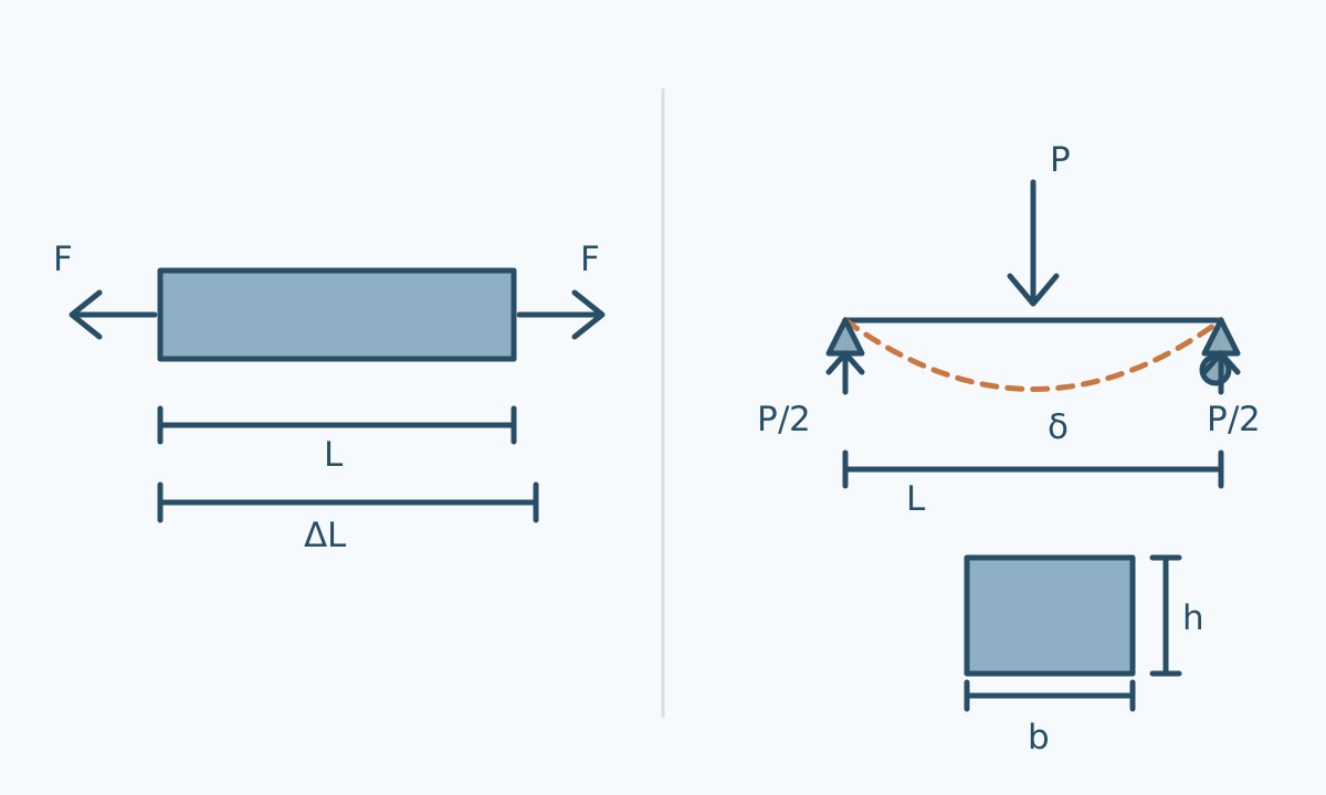
For a uniform tensile specimen, engineering stress is σ = F/A₀ and engineering strain is ε = ΔL/L₀. F is force, A₀ the original cross-sectional area, L₀ the original gauge length and ΔL its extension. Strain is dimensionless: 0.001 equals 0.1%.
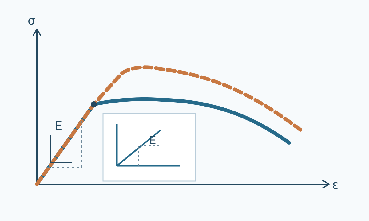
Within an appropriate straight elastic interval, E = Δσ/Δε. The simplified relation σ = Eε assumes the corrected line passes through the origin. Once the response becomes nonlinear, a single straight-line slope no longer describes the whole curve. A tangent modulus refers to a local slope; a chord modulus uses two specified points. State the definition and interval when reporting a result.
Separate material modulus from strength and member stiffness
Yield strength describes the onset of specified permanent deformation; tensile strength is the maximum engineering stress in a tensile test. Neither number can be substituted for E.
Two steel grades can have substantially different yield strengths yet similar elastic moduli. Upgrading to a higher-strength grade therefore does not automatically reduce elastic deflection when geometry, load and supports remain unchanged.
Member stiffness includes geometry. Axial stiffness is EA/L; bending response depends on EI, where I is the second moment of area about the bending axis. Shorter spans and deeper sections can change deflection far more than a small difference in E. Removing thickness to exploit higher strength can reduce stiffness; check both requirements independently.
Choose a value with a stated basis
| Value or source | Meaning and limit |
|---|---|
| E = 200 GPa in the examples below | A declared room-temperature structural-calculation assumption, consistent with SSAB’s typical structural-steel discussion; follow the applicable design standard for a real project. |
| Outokumpu Core 304/4301 and Core 304L/4307: 200 GPa at 20°C | Supplier tabulated physical-property values for the named products; not a universal stainless-steel guarantee. |
| Outokumpu Core 441/4509: 220 GPa at 20°C | A ferritic product example showing why a single value cannot be assigned to all stainless grades. |
| Measured modulus | A test result tied to specimen, orientation, temperature, method, fitted interval and measurement uncertainty. |
Scroll within the table to see all columns →
A nominal or design value is an input chosen under a stated engineering basis. A measured value comes from a particular test. A guaranteed acceptance limit exists only when the applicable specification or agreement establishes one. A certificate reporting yield and tensile strength alone does not establish a measured E.
Temperature changes the input
Alleima’s Sanmac 304/304L billet datasheet gives the following modulus values. They illustrate the behavior of that named product; do not transfer this table to all carbon steels, stainless steels or fire-design cases.
| Temperature (°C) | E (GPa) |
|---|---|
| 20 | 200 |
| 100 | 194 |
| 200 | 186 |
| 300 | 179 |
| 400 | 172 |
| 500 | 165 |
Scroll within the table to see all columns →
For an otherwise identical elastic model, replacing 200 GPa with 165 GPa increases calculated deflection by 200/165 ≈ 1.21. This isolated comparison excludes thermal expansion, changes in strength and restraint, and time-dependent creep. Elevated-temperature design must address those effects separately and use the applicable material and code data.
Worked example: axial extension
Take a uniform bar with F = 10,000 N, A = 200 mm², L = 1,000 mm and E = 200,000 N/mm². Assume concentric loading, room temperature and linear-elastic behavior.
- Stress: σ = F/A = 10,000/200 = 50 MPa.
- Strain: ε = σ/E = 50/200,000 = 0.00025 = 0.025%.
- Extension: ΔL = FL/(AE) = 0.25 mm.
Doubling the area halves the extension. Doubling the length doubles it. Substituting a stronger grade with the same E leaves the elastic extension unchanged. Separately verify that the actual grade remains in the assumed elastic range; this arithmetic is not an allowable-load check.
Worked example: bending deflection
Consider a simply supported, uniform rectangular beam with a central point load P = 500 N and span L = 1,000 mm. The section is b = 50 mm wide and h = 20 mm deep in the bending direction. Use E = 200,000 N/mm², ideal supports, small-deflection Euler–Bernoulli bending and negligible shear deflection; omit self-weight.
- I = bh³/12 = 50 × 20³/12 = 33,333.3 mm⁴.
- Midspan deflection: δ = PL³/(48EI) = 1.5625 mm, about 1.56 mm.
- Maximum moment: M = PL/4 = 125,000 N·mm.
- Maximum bending stress: σ = M(h/2)/I = 37.5 MPa.
At the same width, increasing depth from 20 to 40 mm multiplies I by eight, reducing this calculated deflection to about 0.195 mm. That comparison keeps the applied point load unchanged and continues to omit self-weight. Actual design also checks strength, stability, connections and serviceability limits.
Measure the elastic slope deliberately
ASTM E111-17(2025)e1 covers Young’s, tangent and chord modulus in elastic conditions with negligible creep; its scope excludes initial-tangent-at-origin and secant modulus. The public catalog was checked; the full paid procedure was not reviewed.
For a defensible measurement, resolve the small specimen strain with a suitable extensometer or validated strain system. Crosshead travel can include frame, grip and seating movement. Alignment, gauge length, force and strain calibration, specimen dimensions, temperature and the selected fitting interval can materially change the reported slope. Follow the full applicable method rather than deriving E from an arbitrary pair of noisy points.
A useful report identifies the grade and condition, product form, sampling direction, test temperature, specimen dimensions, strain-measurement method, modulus definition, stress/strain interval, result, units and uncertainty or repeatability information. Dynamic or ultrasonic modulus measurements need their own method context before comparison with a static tensile result.
Apply E without losing the other checks
Start with the governing design rule and the actual material at service temperature. Use supplier data or agreed testing where that basis requires it. Keep units consistent, then check geometry, supports and load case before interpreting a deflection result.
For the practical effects of section thickness, see How to Choose Steel Sheet Thickness . For strength requirements, see How to Choose a Steel Strength Grade .