
Ductility describes the plastic deformation steel can sustain before it fractures. Toughness concerns resistance to fracture and the energy involved, with the meaning fixed by the test method. Brittleness describes fracture with limited plastic deformation under the conditions involved. A steel can show substantial tensile elongation at room temperature and still suffer brittle fracture in a cold, notched or highly constrained component.
Which property does the test measure?
Tensile strength and yield strength describe stress levels; neither supplies a complete measure of ductility or resistance to an existing crack.
| Measurement | Reported quantity | Interpretation boundary |
|---|---|---|
| Elongation after fracture | A, % | Permanent extension over a stated original gauge length; includes localized necking. |
| Reduction of area | Z or RA, % | Contraction at the fractured section; sensitive to specimen and measurement method. |
| Work under a tensile curve | Energy per original volume, commonly MJ/m³ | Depends on the measured stress–strain path and test conditions. |
| Charpy V-notch impact test | Absorbed energy, J | Notched specimen broken by a pendulum at a stated temperature. |
| Plane-strain fracture toughness | KIc, MPa√m | Valid fatigue-precracked test with predominantly linear-elastic behavior and high constraint. |
| Elastic-plastic fracture assessment | JIc, kJ/m²; CTOD, mm | Crack-initiation or crack-growth resistance with parameter-specific validity requirements. |
Scroll within the table to see all columns →
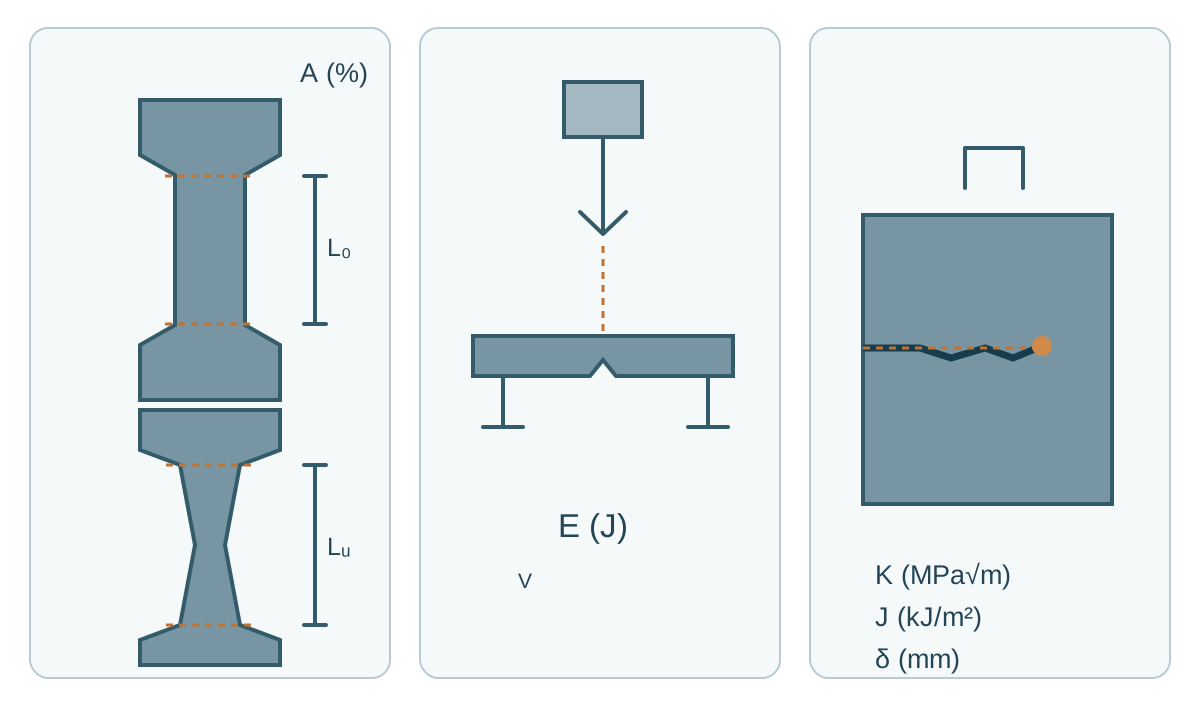
Reading tensile ductility correctly
For elongation after fracture, fit the broken pieces together as the test method requires and compare the final gauge length Lᵤ with the original L₀. Reduction of area compares the original section S₀ with the smallest section Sᵤ after fracture:
A = 100 × (Lᵤ − L₀) / L₀
Z = 100 × (S₀ − Sᵤ) / S₀
In a calculation example, L₀ = 50 mm and Lᵤ = 62.5 mm give A = 25%. If S₀ = 80 mm² and Sᵤ = 40 mm², Z = 50%. These percentages describe different geometric changes; their numerical values need not agree.
Uniform elongation refers to extension at maximum force; substantial diffuse necking develops from this stage. The term does not imply identical strain at every point along the gauge length. Elongation after fracture includes the neck’s contribution. An extensometer result at fracture may also include elastic strain; check the reported symbol and method before comparing it with a length measured after unloading. A longer gauge length distributes the localized extension over a greater original length and can lower the reported percentage for otherwise comparable specimens. Keep gauge length, cross-section, orientation and test temperature matched. ASTM E8 and E8M use different gauge-length conventions for most round specimens; converting inches into millimetres does not resolve that difference.
Sheet formability also depends on the strain path, edge quality, bending geometry and local fracture resistance. A tensile elongation value alone cannot establish a minimum bend radius or a safe forming limit.
Tensile energy and Charpy energy
The area under an engineering stress–strain curve to fracture represents work per original gauge volume when stress and gauge strain are defined consistently. Use strain as a fraction: integrating stress in MPa then gives MJ/m³. Integrating a percent-strain axis without dividing by 100 produces a factor-of-100 error. After necking, this remains a specimen-level work measure; strain inside the neck is highly nonuniform. Multiplying tensile strength by elongation does not reproduce the area under the actual curve.
A Charpy test measures the energy absorbed during impact of a notched bar. A common full-size V-notch specimen is 55 × 10 × 10 mm with a 2 mm notch depth; the pendulum strikes the face opposite the notch. The reported energy in joules depends on specimen size, notch and striker geometry, orientation and temperature. ASTM E23 and ISO 148-1 describe test methods; the applicable product or construction specification supplies acceptance criteria.
Subsize specimens can be necessary for thin products. Their energies and transition behavior require the applicable specified treatment; a simple area-ratio conversion can mislead. Report individual energies and any required average, plus specimen dimensions and test temperature. The energy supplies no direct universal conversion to KIc or JIc.
What fracture toughness adds
Fracture-mechanics testing introduces a sharp fatigue precrack and measures resistance to crack initiation or extension. KIc applies when the prescribed plane-strain and predominantly linear-elastic validity conditions are satisfied. Its unit MPa√m combines stress with the square root of length. A provisional KQ result becomes KIc only after the required checks. ASTM E399 is the relevant KIc method; its current scope excludes cleavage-fracture characterization.
Where appreciable plasticity accompanies fracture, J and crack-tip opening displacement (CTOD) provide other descriptions. J has units of energy per crack area: 1 kJ/m² = 1 N/mm. A qualified JIc characterizes initiation of stable tearing; a J-resistance curve describes the evolution with crack extension. CTOD is a displacement, commonly in millimetres. ASTM E1820 addresses these measurements, while ASTM E1921 provides a framework for ferritic steels undergoing cleavage in the transition region.
Using these values in a component assessment also requires flaw size, geometry, applied and residual stress, temperature and loading history. Cyclic loading and environmental cracking need their own treatment. A high elongation result cannot answer a crack-tolerance question by itself.
Conditions that promote brittle behavior
Low temperature, rapid loading and high crack-tip constraint can favor cleavage fracture in susceptible ferritic steels. Thickness and crack geometry influence constraint, limiting plastic deformation around a crack tip. The balance also changes with composition, grain structure and processing history.
- Grain refinement often improves resistance to cleavage in ferritic steels; grain coarsening can impair it.
- Cold work changes strength and remaining ductility. Heat treatment changes phases and their distribution; its effect on toughness depends on the grade and treatment cycle.
- Welding creates locally different weld-metal and heat-affected-zone properties. A parent-plate certificate cannot describe every region of a welded joint.
- Inclusions, segregation and embrittling exposure can reduce local resistance to fracture. The test material should match the supplied or service-exposed condition.
Ferritic steels commonly show a temperature range over which fracture behavior changes. A transition temperature must identify its criterion, such as a specified absorbed energy or shear-fracture fraction, and the test configuration. Different criteria and specimen sizes can give different temperatures. Austenitic stainless steels generally retain useful low-temperature toughness without the same pronounced ferritic transition; grade, product condition and welds still require qualification.
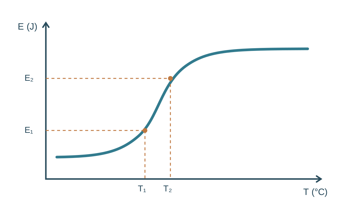
A Charpy test at −20°C does not by itself authorize operation at −20°C. Service assessment considers the design rules, minimum metal temperature, section thickness, stress, flaws, fabrication and loading. Hardness also cannot establish toughness through a universal conversion.
What to check in a test report
- Identify the grade, heat or batch, product thickness, delivery condition and sampled location. Keep parent metal, weld metal and heat-affected zone distinct.
- For elongation, record the test standard, specimen direction and geometry, original gauge length and whether the value is uniform, at fracture or after fracture.
- For Charpy, record the standard edition, specimen and notch dimensions, orientation, striker configuration, temperature, individual results and required acceptance rule.
- For fracture toughness, identify the parameter, precrack orientation, test temperature and loading rate, specimen dimensions and validity statement. Retain provisional labels when requirements are unmet.
- Compare with the exact product and project requirements. US, UK, Australian and Canadian projects can invoke different standards and editions; a country label alone establishes no equivalence between reports.
For example, “25% elongation over 50 mm” and “60 J at −20°C” answer separate questions. Without the remaining test details, neither value establishes a complete ductility ranking, a design fracture-toughness value or a minimum service temperature. The strength-grade selection guide connects these report checks to specification, while S275 versus S355 explains the grade-specific context.