
Choose metal-roof fasteners from the complete connection: the panel, supporting material, screw or clip, washer and approved fastening schedule. A spacing dimension becomes usable only when its direction, roof zone and connection type are identified. There is no universal screw spacing for metal roofing.
This guide helps purchasers and qualified roofing teams read an attachment schedule and resolve missing information. The separate sheet-installation guide covers work sequence. Here the focus is the connection and the evidence needed to accept it.
Identify the connection before choosing a screw
| Connection | Specify | Confirm before use |
|---|---|---|
| Sheet to support | Substrate-compatible screw and washer | Engagement and approved load path |
| Sheet side-lap | Specified stitch fastener | Lap detail and spacing |
| Concealed attachment | Specified clip and clip fasteners | Substrate fixing and movement |
| Flashing or trim | Detail-specific fastener | Attachment, weathering and compatibility |
Scroll within the table to see all columns →
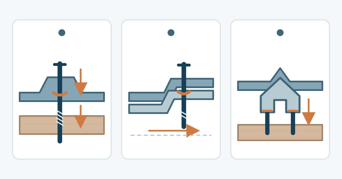
Panel-to-support screws carry loads into the specified substrate. Stitch screws join adjacent sheet edges; their purpose and placement come from the panel detail. A lap screw alone does not establish attachment to a purlin. Concealed systems use the specified clips or other concealed attachments, and the screws fixing those components also need a verified substrate connection. Standing-seam and corrugated systems use different attachment arrangements.
Check the exact product designation, diameter, thread form, drill point, length, head and washer. A matching head colour or socket size does not establish interchangeability. Keep panel, lap and clip fasteners separately identified on the order and on site.
Match drilling, clamping and engagement to the substrate
For steel supports, confirm the support thickness and the fastener’s documented drilling range. Also check the permitted clamping thickness and required thread projection or engagement. These are different limits: a screw can be long enough to reach the support yet have the wrong drill point for it. Include the actual panel stack and any specified intervening components when checking the connection.
For timber, use a fastener accepted for the timber connection, with the specified effective threaded embedment into sound wood. The tapered tip, roof sheet and insulation do not supply that embedment. Plywood or OSB decking needs the documented deck-attachment detail; do not substitute a solid-timber rule. For either substrate, degraded material or stripped holes require an accepted repair before fastening resumes.
Record steel thickness in the basis required by the manufacturer. A gauge label alone can be ambiguous; base-metal thickness and roof-sheet selection are separate from screw diameter. Do not transfer a screw capacity from a different support thickness or material.
Separate the four meanings of spacing
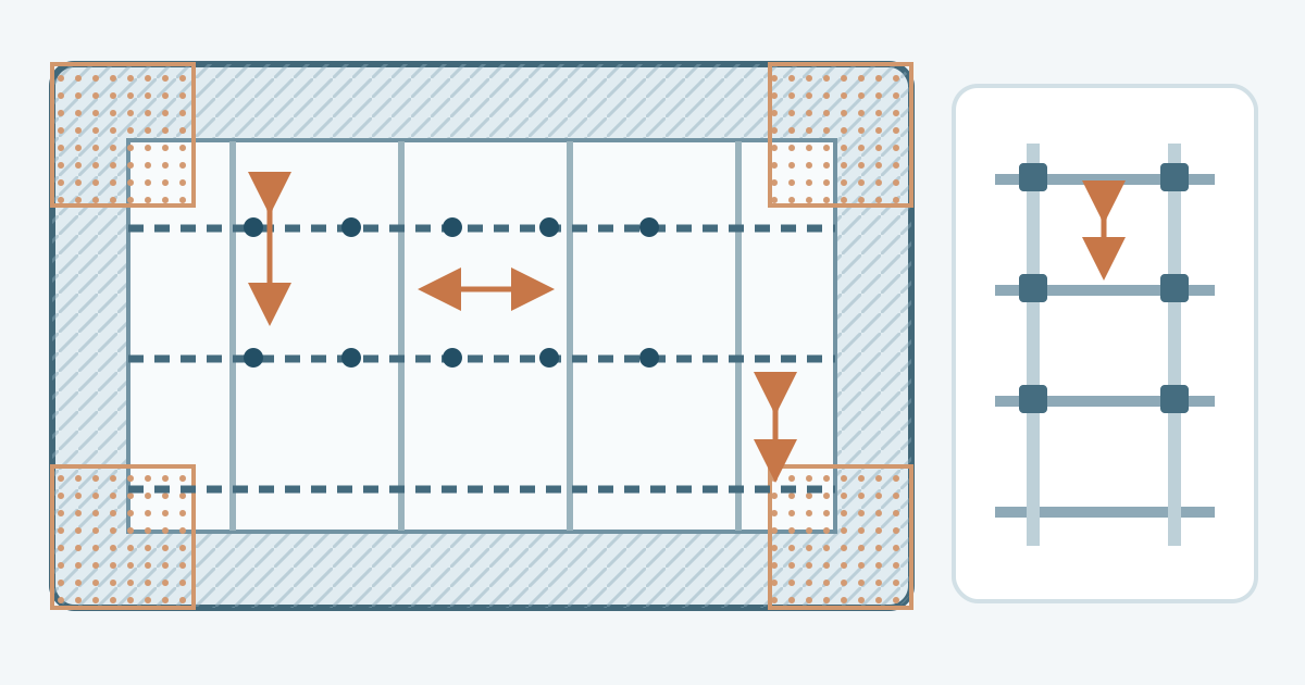
A useful drawing distinguishes support spacing along the roof slope, fastener positions across each panel at a support, stitch spacing along a lap, and clip spacing for a concealed system. A dimension attached to one of these cannot fill a blank in another. Read whether dimensions are centre-to-centre and identify the starting and ending positions.
The roof plan must also identify field, perimeter and corner zones with their applicable attachment details. Wind demand and the approved assembly determine the schedule; the widths of those zones and any enhanced attachment must come from the project design. Do not invent an edge strip or copy the field pattern everywhere. Crest versus pan placement is profile-specific; neither location is a universal roofing rule.
For example, a note giving purlin spacing still leaves the fastener pattern across each sheet unresolved. A separate side-lap detail does not resolve that omission. Request the relevant connection drawing and zone schedule before ordering quantities or drilling holes.
Read capacity evidence as a connection check
Pull-out concerns the fastener withdrawing from its support. Pull-over concerns the sheet failing around the head or washer. A strong screw can still be part of a weak connection if the support, sheet or clip governs. Also establish the applicable shear and combined-load checks where the design requires them.
When comparing data, match the substrate, thickness, panel material, washer, installation and test basis. Identify whether the published number is an ultimate test result, characteristic resistance or allowable/design value; these labels are not interchangeable. Obtain the permitted design value and complete assembly evidence from the responsible designer or supplier. Multiplying a catalogue pull-out figure by a guessed screw count does not establish roof uplift resistance. This guide supplies no structural sizing formula or substitute wind design.
Check corrosion compatibility and movement
Specify fastener material and protective finish for the panel coating, support and exposure. Stainless steel is not an automatic upgrade for every coated-steel roof: compatibility must cover the complete assembly and environment. Confirm washer material, backing and service suitability with the system supplier. The galvanic-corrosion explanation describes why dissimilar-metal contact needs context.
In concealed systems, identify fixed and sliding details and any permitted clip travel. Additional screws must not restrain a detail intended to move. Sheet length and thermal expansion matter, but a thermal calculation alone cannot establish a usable clip arrangement.
Inspect seating and deal with defects
Install with the specified driver and settings, keeping the fastener perpendicular to its seating surface. The washer must seat evenly without a gap, excessive extrusion or damage to the panel. Under-driving can leave an incomplete seal; over-driving can damage the washer, strip the connection or distort the sheet. A single torque setting cannot be assumed suitable for every substrate and screw.
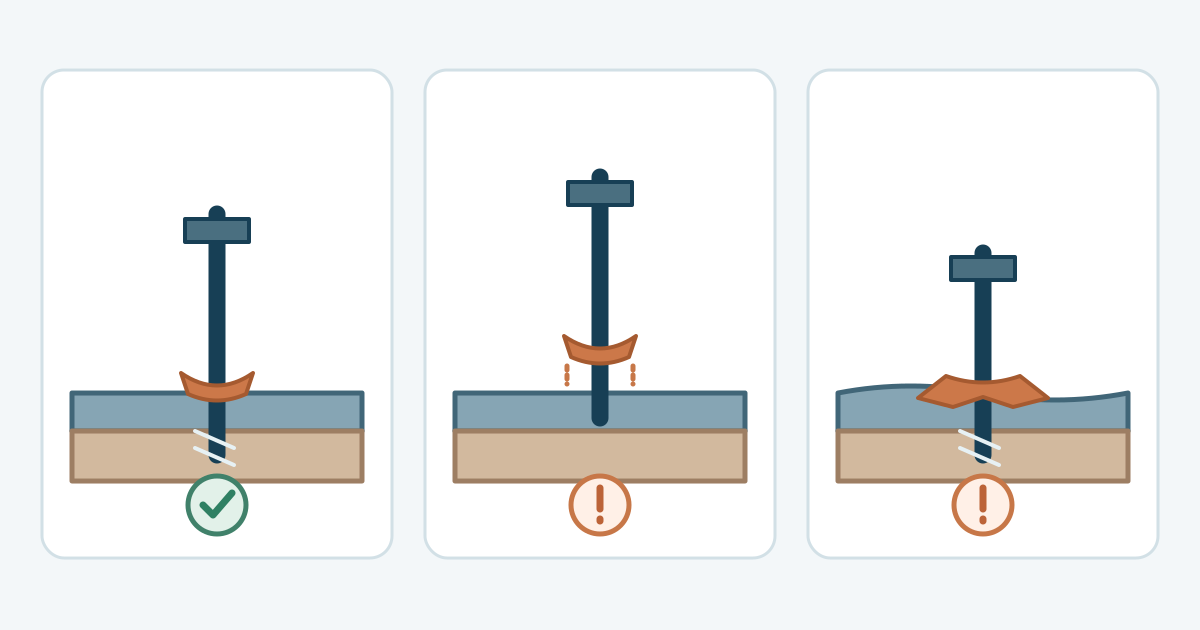
Check a trial connection under the manufacturer’s procedure, then inspect the work as conditions change. Record missing or tilted screws, damaged seals, stripped threads, misplaced holes and metal swarf. Obtain an approved repair detail; do not assume sealant alone restores connection strength or that a larger screw is always acceptable. Plan inspection with safe access and fall protection, following local requirements.
Release an order with a traceable schedule
Before ordering, record the panel/profile and coating; support material and thickness; each fastener’s full designation; washer; required engagement; roof-zone drawings; support, panel, lap and clip patterns; movement details; and approved substitutions. Count each connection category from those drawings and state how spares are handled. A universal screws-per-area allowance cannot resolve an incomplete design.
Use the manufacturer’s current product and market documentation. US, UK, Australian and Canadian approval or wind-design bases may differ; a foreign installation drawing does not establish local compliance. Resolve conflicts with the project designer and supplier before work proceeds. The checked references identify the public documents used and their limits.