
Install profiled metal roofing from a checked roof plan, using the selected manufacturer’s current details at every stage. Verify the supports and safe access first, establish the first sheet accurately, then complete fastening, laps and weathering details in controlled sections. Inspect work while joints remain visible.
This sequence is for qualified roofing teams and those checking their work. The approved assembly determines dimensions and fixings. This guide supplies no universal screw spacing, lap length, minimum slope or crest-versus-pan rule. System selection , sheet thickness and profile dimensions have separate guides.
1. Assemble a usable installation brief
Identify the exact profile, base-metal thickness, coating, sheet lengths and support material. Collect the current installation manual, project roof plan, wind-zone fastening schedule and accepted flashing details. A retailer’s product name or a previous job’s screw pattern leaves essential information unresolved. Confirm that structural evidence covers the actual substrate and support arrangement.
Use the following record to prepare the installation briefing. Enter drawing or manual references and the responsible person’s approval before releasing each work area.
| Item | Record for this roof | Hold work when |
|---|---|---|
| Geometry and drainage | Measured slope, eaves, valleys, penetrations and approved sheet lengths | The roof falls outside the named product's documented limits. |
| Support and load path | Support material, thickness, spacing, alignment and edge-zone requirements | Installed supports differ from the approved assembly. |
| Attachments | Panel screws or clips, lap fasteners, washers and substrate engagement | A substitution lacks acceptance for this assembly. |
| Weathering and movement | Lap, closure, flashing, penetration and movement drawings | A junction or required movement detail is missing. |
| Access and inspection | Lifting, fall protection, weather limits, rescue and inspection responsibilities | The crew cannot work or inspect the area safely. |
Scroll within the table to see all columns →
Manufacturer manuals cover particular products and markets. For example, the LYSAGHT general manual principally addresses non-cyclonic applications; its standard details cannot establish suitability for a different wind region. Resolve conflicting documents with the supplier and project designer before installation.
2. Establish access and receive the sheets
Plan edge protection, openings and rooflights, access equipment, lifting and exclusion areas before unloading. HSE advises treating fixed roofs as fragile until a competent person confirms otherwise. Follow local working-at-height requirements and a task-specific rescue plan. A harness requires suitable anchorage and a complete protection system; a sheet or clip is not automatically an anchor. Include protection against sharp edges, flying fragments and handling injuries. Stop when weather exceeds the safe-work limits. The safety sources address different jurisdictions and do not replace local requirements.
Check delivered labels, quantity, lengths and damage against the order. Keep bundles supported, dry and ventilated under the supplier’s storage instructions. Separate and dry wet sheets as instructed. Plan lifts for the sheet length and wind conditions; prevent dragging, bending and coating damage. Obtain approval for roof-level bundle loads and their locations. Do not assume that a support able to carry the finished roof can carry a concentrated delivery bundle.
3. Accept the supports and concealed layers
Check the actual supports for condition, spacing, straightness and alignment in the required plane. Measure the roof slope and confirm eaves and ridge geometry against the drawings. Escalate rotten timber, corroded members, inadequate fixing thickness or misplaced supports. Pulling sheets down onto an uneven frame can distort the finished roof.
Install the specified underlay, insulation, air or vapour-control layers and any required ventilation components in their designed sequence. Confirm continuity at eaves, valleys and penetrations before covering them. The roof build-up depends on climate and occupancy; adding an arbitrary membrane can leave condensation control unresolved. Check compatibility between the coating, supports, accessories and water draining from adjacent materials. Photograph concealed work and record accepted repairs before proceeding.
4. Set the first sheet and control alignment
Check the weather face, overlap edge and laying direction on the ground. Product geometry and the approved plan determine the sequence; prevailing weather is one consideration where the manufacturer’s details allow a choice. Establish a reference line, sheet overhang and end position from the drawings. Fit any eaves or valley components that must precede the sheets. Form required sheet-end turn-ups or downturns at the stage and with the tools specified for the profile.
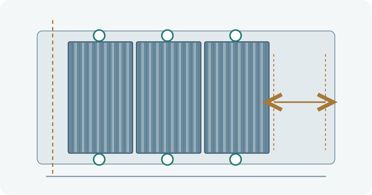
Align and secure the first sheet by the specified method. Check subsequent sheets against the reference at both ends, including their effective cover and the remaining width to the finishing edge. A straight eaves line alone can conceal cumulative skew. Stop and correct an alignment error within the supplier’s tolerances before forcing ribs together or drilling a displaced fixing line.
5. Install the specified attachments
Separate sheet-to-support fasteners from side-lap or flashing fasteners. Their length, thread, drilling capacity, washer and corrosion compatibility serve different connections. Verify them against the actual timber or steel support. ASC’s fastener guide distinguishes these applications and directs installers to the relevant attachment schedules.
Follow the named product’s fixing position and zone-specific pattern. For example, the Australian LYSAGHT TRIMDEK document specifies crest fixing for roofing; that instruction must stay with that product and application. Other profiles require their own details. Clip-fixed systems also need the exact clip, orientation, attachment and engagement sequence.
Use the prescribed driver and adjustment. Keep gasketed screws square to the local sheet surface and seat the washer as specified without crushing it or leaving it loose. Check a representative installed fixing before repeating the operation. A missed support, stripped thread, damaged washer or distorted sheet needs an accepted repair; extra tightening cannot restore a stripped connection. Complete the required attachments as work advances and secure unfinished areas under the site plan.
6. Make laps and weathering junctions deliberately
Nest side laps in the correct orientation and preserve any designed anti-capillary or drainage channel. Follow the specified stitching and seal arrangement. Where end laps are permitted, confirm their support position, overlap, sealing and installation order from the product detail. Some concealed-fixed profiles prohibit conventional end laps. A convenient sheet joint is not evidence that the joint is permitted.
Use compatible sealant or tape on surfaces prepared as its manufacturer requires. Check bead location and joint closure while visible; keep designed drainage paths clear. The drawings must coordinate eaves, ridges, valleys, walls, closures and penetrations. Some flashing components are fitted before the sheets and others afterwards. Match the sequence to each junction.
A pipe boot or large opening needs an accepted detail for water flow, substrate support and movement. Arrange additional framing or drainage components where the design calls for them. Obtain approval before cutting a new opening; a bead of surface sealant cannot resolve missing support or obstructed drainage.
7. Preserve movement and remove cutting debris
Check the approved sheet-length limits, fixed points, clips and movement joints before closing flashings. Through-fastened and clip-fixed assemblies accommodate movement differently. A later fastener, rigid flashing or accessory can restrain the intended travel. The thermal-expansion guide explains the principle; the roof-system supplier must provide the installation allowance. Do not enlarge holes or omit fixings as an improvised movement detail.
Use the cutting method permitted for the coating and profile. Protect adjacent finished surfaces and collect swarf from cutting and drilling promptly, including debris trapped at laps and gutters. Metal Sales’ Classic Rib guide recommends snips or shear-type tools and cleaning installed surfaces at each work period’s end. Apply the supplier’s damage assessment and repair instructions; large coating damage may require replacement.
8. Close inspection and hand over a traceable roof
Inspect safely with the supervisor before access is removed. Use the table to connect each observation to its drawing or specification and record any corrections. A tidy appearance leaves concealed connections unverified.
| Check | Look for | Retain |
|---|---|---|
| Attachments | Correct locations, completed patterns, sound washers and engaged clips | Zone schedule, inspection record and accepted repairs |
| Weathering | Closed laps, correct flashings, clear drainage and completed penetrations | Detail references and photographs before concealment |
| Movement | Specified clearances and fixed points, with no unintended restraint | Movement details and accessory approvals |
| Surface and housekeeping | Coating damage, swarf, offcuts and blocked gutters | Repair decisions and final clean-up record |
| Owner handover | Safe inspection access and a product-specific maintenance plan | Product identities, document revisions, warranties and service contacts |
Scroll within the table to see all columns →
Record unresolved defects with an owner and an agreed correction method. Any specified water test needs its own approved procedure and safe access; a visual inspection alone does not establish watertightness under every condition. Give the owner the final roof drawings, product documents, inspection records and maintenance requirements. Keep future rooftop equipment changes subject to structural, weathering and movement review.