
Remove weld heat tint by selecting a treatment that removes the oxide and the chromium-depleted surface beneath it, then verify the result against the component’s service and finish requirements. Chemical pickling, suitable electrochemical treatment or a qualified mechanical sequence may be appropriate. Cleaning away grease, making a weld shiny and carrying out chemical passivation have different purposes.
This guide is for specifying and supervising professional post-weld surface treatment. Industrial pickling products can cause severe injury. Their use requires competent personnel, a product-specific procedure and controlled facilities; this article is not an operating instruction for handling acids.
1. Define the condition and the required result
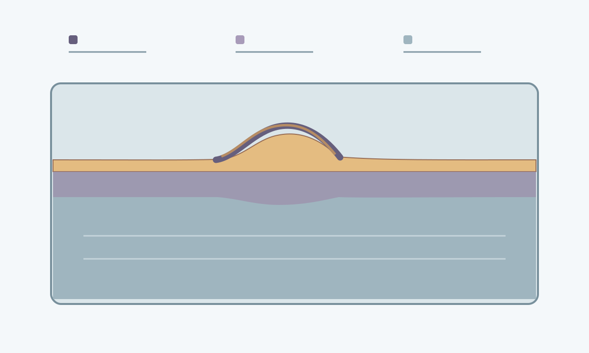
Heat tint is the coloured oxide around a heated stainless surface. The affected area may include the weld face, adjacent heat-affected zone and internal root. Chromium depletion beneath the oxide can reduce local corrosion resistance. A colour photograph cannot establish removal depth, remaining corrosion resistance or the temperature reached during welding.
Record the grade, material thickness, existing finish, weld locations and accessible faces. Confirm exposure to water, chlorides, process chemicals or cleaning agents. A decorative indoor panel and a wetted process vessel need different acceptance plans. Components designed for high-temperature oxidation service need a service-specific assessment rather than an automatic cosmetic cleanup rule.
Use the applicable contract or fabrication specification. There is no universal acceptable heat-tint colour for every grade and service. Escalate heavy scale, pitting, cracks, poor root geometry or suspected metallurgical damage to the responsible engineer; surface treatment cannot resolve every weld defect.
2. Compare methods by what they must achieve
| Treatment | Potential use | Qualification concern |
|---|---|---|
| Chemical pickling | Removal of oxide and affected surface metal on compatible stainless grades | Product suitability, finish change, access, complete residue removal and controlled waste |
| Electrochemical weld cleaning | Local treatment using a defined equipment and electrolyte system | Demonstrate removal capability for the actual tint, grade, weld profile and acceptance criteria |
| Mechanical treatment | Controlled removal where access, finish and remaining section allow it | Residual affected metal, embedded contamination, roughness, overheating and loss of section |
| Chemical passivation after suitable preparation | Specified contamination removal and support for the passive surface condition | Ordinary passivation alone is not a substitute for removing heat-tint oxide and affected metal |
Scroll within the table to see all columns →
Do not assume every brush-type electrochemical cleaner performs the same operation as a qualified electropolishing process. Likewise, a stainless wire brush or fine abrasive pad that changes appearance has not demonstrated complete treatment. Degreasing remains a separate preparation step wherever oil or other organic contamination is present.
3. Qualify a representative trial
Give the treatment specialist a representative welded coupon or an agreed trial area. It should reproduce the grade, finish, tint severity, weld profile and access limitations. A flat coupon alone may miss a difficult internal corner or root.
Agree the inspection sequence before treatment. Compare the resulting texture, brightness and dimensional condition with the drawing or approved sample. Where corrosion performance is critical, have the responsible specialist select an appropriate qualification or acceptance test and define its sampling and limits. A successful trial establishes a controlled method for that condition; it does not automatically qualify other grades, products or equipment settings.
4. Establish the safety and waste arrangements
Assign the work to trained personnel using the current safety data sheet and an approved procedure. The risk assessment must cover exposure control, ventilation, suitable protective equipment, segregation of adjacent materials, emergency response and waste handling. Hydrofluoric-acid-containing products present particularly serious hazards. Safer alternatives still need their own assessment.
The facility must be able to contain treatment residues and rinse water, including contamination released from the metal. Do not discharge them into ordinary drains. Arrange compliant collection and treatment before starting. Stop when the site, access or emergency arrangements cannot support the selected process.
5. Use a controlled treatment sequence
The work instruction should assign these eight checkpoints without replacing the supplier’s operating procedure:
- Identify the component, grade, welds, treatment boundaries and acceptance specification.
- Inspect for weld defects and photograph accessible faces and roots before treatment.
- Remove oil and other interfering contamination with a compatible preparation process.
- Confirm the qualified treatment, trained operator, equipment condition and safety controls.
- Treat the specified surfaces while protecting required weld geometry, dimensions and adjacent finishes.
- Complete the specified residue-removal and rinsing stages, with access and drainage adequate for all treated areas.
- Complete any separately specified passivation or finishing stage, then clean and dry as required.
- Inspect, record results and hold nonconforming areas for an approved correction and repeat inspection.
There is no transferable acid concentration, contact time, abrasive sequence or machine setting for all stainless welds. Those details belong in the qualified product- and component-specific procedure.
6. Include the root and protect the finish
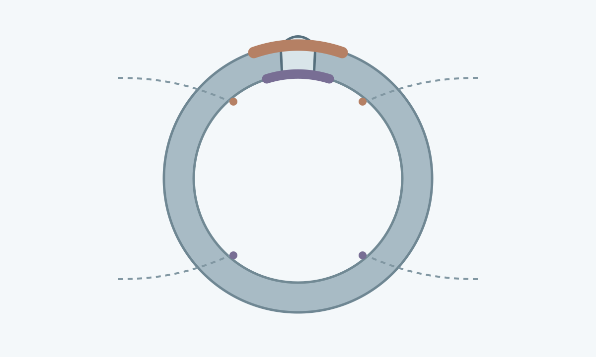
For pipework, tanks and hollow fabrications, map the surfaces that contact the service environment. A bright external weld can hide untreated root tint. Decide how the internal treatment and inspection will be performed before assembly closes access. A borescope can document accessible internal appearance, but it does not itself prove corrosion performance.
Check places that can retain liquids, including joints, crevices and dead ends. If complete treatment and residue removal cannot be demonstrated, revise the fabrication or treatment plan with the responsible engineer.
Pickling can leave a different brightness; mechanical blending can alter grain direction and local thickness. Do not grind a weld flush unless the design permits it. For detailed appearance control, use the separate stainless-sheet polishing guide .
7. Verify more than the visible colour
Inspect the complete agreed area under suitable lighting, including edges of the treated zone. Look for remaining oxide, streaking, new pits, abrasive marks, trapped residue and damage to the required finish. Check dimensions and roughness where specified.
ASTM A380/A380M-25 addresses cleaning and surface-treatment practice; ASTM A967/A967M-25 covers chemical passivation treatments and associated verification options. The agreed specification and applicable full standard determine the method and acceptance criteria. A free-iron test addresses contamination; it does not by itself prove removal of a chromium-depleted layer or suitability for every corrosive service. A water-break check concerns surface cleanliness and likewise has limited scope.
8. Record acceptance and reduce repeat work
The release record should identify the component and grade, procedure revision, treatment areas, product or equipment system, operator, inspection results and any rework. Record inaccessible areas explicitly. Retain agreed photographs or sample references and protect the cleaned component from carbon-steel debris during handling and storage.
Repeated tint problems should trigger review of shielding, root protection, joint access and the approved welding procedure. Prevention reduces cleanup demand, while final acceptance still follows the specified surface condition. See stainless-steel welding for upstream controls and stainless-grade selection when the service environment itself remains uncertain.